Chapter: RF and Microwave Engineering : Microwave Tubes and Measurements
Reflux Klystron
REFLUX KLYSTRON
If a fraction of the output power is fed back
to the input cavity and if the loop gain has a magnitude of unity with a phase
shift of multiple 27T, the klystron will oscillate. However, a two-cavity
klystron oscillator is usually not constructed because, when the oscillation
frequency is varied, the resonant frequency of each cavity and the feedback
path phase shift must be readjusted for a positive feedback.
The reflex klystron is a single-cavity klystron
that overcomes the disadvantages of the twocavity klystron oscillator. It is a
low-power generator of 10 to 500-mW output at a frequency range of I to 25 GHz.
The efficiency is about 20 to 30%. This type is widely used in the laboratory
for microwave measurements and in microwave receivers as local oscillators in
commercial, military, and airborne Doppler radars as well as missiles.
The theory of the two-cavity klystron can be
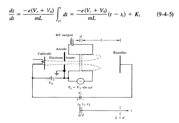
applied to the nalysis of the reflex klystron with slight modification. A
schematic diagram of the reflex klystron is shown in Fig. 9-4-1.
The electron beam injected from the cathode is
first velocity-modulated by the cavity-gap voltage. Some electrons accelerated
by the accelerating field enter therepeller space with greater velocity than
those with unchanged velocity. Some electrons decelerated by the retarding
field enter the repeller region with less velocity.
All electrons turned around by the repeller
voltage then pass through the cavity gap in bunches that occur once per cycle.
On their return journey the bunched electrons pass through the gap during the
retarding phase of the alternating field and give up their kinetic energy to
the electromagnetic energy of the field in the cavity. Oscillator output energy
is then taken from the cavity. The electrons are finally collected by the walls
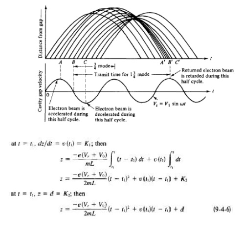
of the cavity or other grounded metal parts of the tube. Figure 9-4-2 shows an
Applegate diagram for the 1~ mode of a reflex klystron.
Velocity Modulation
The analysis of a reflex klystron is similar to
that of a two-cavity klystron. For simplicity, the effect of space-charge
forces on the electron motion will again be neglected. The electron entering
the cavity gap from the cathode at z
= 0 and time to is assumed to have
uniform velocity
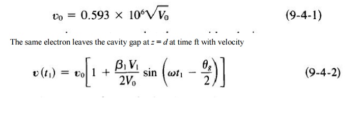
This expression is identical to Eq. (9-2-17),
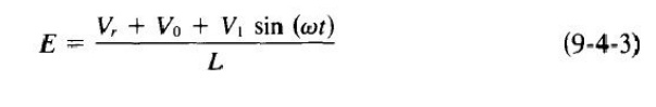
for the problems up to this point are identical to those of a two-cavity
klystron amplifier. The same electron is forced back to the cavity z = d
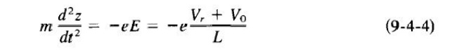
and time tz by the retarding electric
field E, which is given by
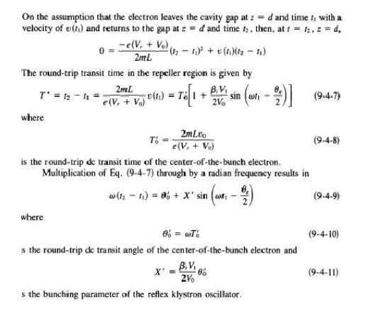
This retarding field E is assumed to be constant in the z direction. The force equation for one electron in the repeller
region is
where E = - VY is used in the z direction only, Yr is the magnitude of the repeller voltage, and I Yt sin wt I ~ (Yr + Yo) is assumed. Integration
of Eq. (9-4-4) twice yields
t0 time for electron entering cavity gap at z = 0
t 1 time for same electron leaving cavity gap at z =
d time for same electron returned by retarding field
z = d and collected on walls of cavity
Related Topics