Chapter: RF and Microwave Engineering : Microwave Tubes and Measurements
Measurement of Power
MEASUREMENT OF POWER
Power
Measurement
ü Power is defined as the quantity of energy
dissipated or stored per unit time.
ü Microwave power is divided into three
categories – low power (less than 10mW), medium power (from 10mW to 10W) and
high power (greater than 10w).
ü The general measurement technique for average
power is to attach a properly calibrated sensor to the transmission line port
at which the unknown power is to be measured.
ü The output from the sensor is connected to an
appropriate power meter. The RF power to the sensor is turned off and the power
meter zeroed. This operation is often referred to as “zero setting” or
“zeroing.” Power is then turned on.
ü The sensor, reacting to the new input level,
sends a signal to the power meter and the new meter reading is observed.
ü There are three popular devices for sensing and
measuring average power at RF and microwave frequencies. Each of the methods
uses a different kind of device to convert the RF power to a measurable DC or
low frequency signal. The devices are the diode detector, the bolometer and the
thermocouple.
Diode
Detector
The low-barrier Schottky (LBS) diode technology
which made it possible to construct diodes with metal-semiconductor junctions
for microwave frequencies that was very rugged and consistent from diode to
diode. These diodes, introduced as power sensors in 1974, were able to detect
and measure power as low as −70 dBm (100 pW) at frequencies up to 18 GHz.
Bolometer
Sensor:
Bolometers are power sensors that operate by
changing resistance due to a change in temperature. The change in temperature
results from converting RF or microwave energy into heat within the bolometric
element. There are two principle types of bolometers, barretters and
thermistors. A barretter is a thin wire that has a positive temperature
coefficient of resistance. Thermistors are semiconductors with a negative
temperature coefficient.
Thermistor elements are mounted in either
coaxial or waveguide structures so they are compatible with common transmission
line systems used at microwave and RF frequencies.
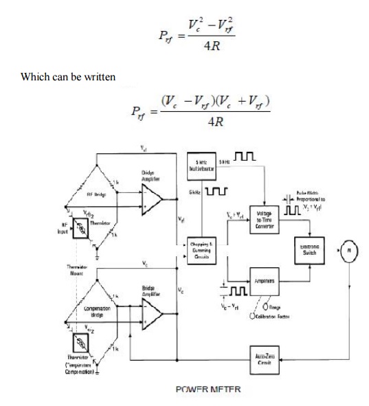
Power meters are constructed from balanced
bridge circuits. The principal parts of the power meter are two self-balancing
bridges, the meter-logic section, and the auto-zero circuit. The RF Bridge,
which contains the detecting thermistor, is kept in balance by automatically
varying the DC voltage Vrf, which drives that bridge. The compensating bridge,
which contains the compensating thermistor, is kept in balance by automatically
varying the DC voltage Vc, which drives that bridge. The power meter is
initially zero-set (by pushing the zero-set button) with no applied RF power by
making Vc equal to Vrfo (Vrfo means Vrf with zero RF power). After
zero-setting, if ambient temperature variations change thermistor resistance,
both bridge circuits respond by applying the same new voltage to maintain
balance.
If RF power is applied to the detecting
thermistor, Vrf decreases so that
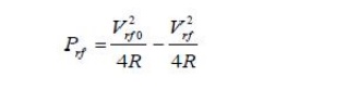
Where Prf is the RF power applied and R is the
value of the thermistor resistance at balance. But from zero-setting, Vrfo= Vc
so that
Thermocouple
Sensors
Thermocouple sensors have been the detection
technology of choice for sensing RF and microwave power since their
introduction in 1974. The two main reasons for this evolution are: 1) they
exhibit higher sensitivity than previous thermistor technology, and 2) they feature
inherent square-law detection characteristic (input RF power is proportional to
DC voltage out).
Since thermocouples are heat-based sensors,
they are true “averaging detectors.” Thermocouples are based on the fact that
dissimilar metals generate a voltage due to temperature differences at a hot
and a cold junction of the two metals. The power sensor contains two identical
thermocouples on one chip, electrically connected as in Figure.
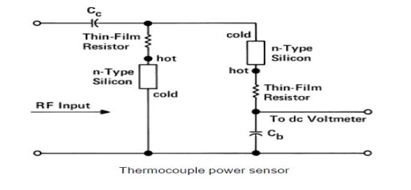
The thermocouples are connected in series as far as the DC voltmeter is concerned. For the RF input frequencies, the two thermocouples are in parallel, being driven through coupling capacitor Cc. Half the RF current flows through each thermocouple.
Each thin-film resistor and the silicon in
series with it have a total resistance of 100 Ω. The two thermocouples in
parallel form a 50 Ω termination to the RF transmission line. The lower node of
the left thermocouple is directly connected to ground and the lower node of the
right thermocouple is at RF ground through bypass capacitor Cb. The DC voltages
generated by the separate thermocouples add in series to form a higher DC
output voltage. The principal advantage, however, of the two thermocouple
scheme is that both leads to the voltmeter are at RF ground; there is no need
for an RF choke in the upper lead. If a choke were needed it would limit the
frequency range of the sensor. For a square wave modulated signal the peak
power can be calculated from the average power measured as where T is the time
period and Շ is the pulse width. Y P peak av P.
Related Topics