Chapter: RF and Microwave Engineering : Microwave Tubes and Measurements
Measurement of Wavelength and Impeadence
MEASUREMENT OF WAVELENGTH AND IMPEADENCE
The impedance at any point on a transmission line can be written in the form R+jX For comparison SWR can be calculated
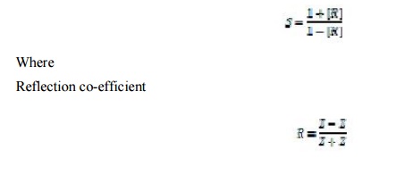
Z0= characteristics impedance of w/g at operating frequency
Z= load impedance. The measurement is performed in following way.
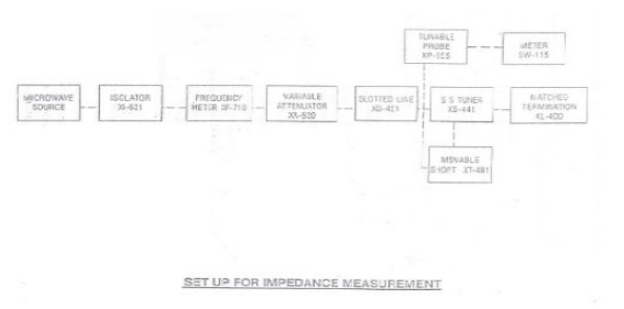
The unknown device is connected to the slotted line and the position of one minima is determined. The unknown device is replaced by movable short to the slotted line . Two successive minima positions are noted.The twice of the difference between minima position will be guidewave length. One of the minima is used as reference for impedance measurement .find the difference of reference minima and minima position obtained from unknown load. Let it be ‘d’. Take a smith chart , taking ‘1’ as centre, draw a circle of radius equal to S. mark a point on circumference of smith chart towards load side at a distance equal to d/g. join the centre with this point . find the point where it cut the drawn circle.the co-ordinates of this point will show the normalized impedance of load.
PROCEDURE:
1.Setup the components and equipments as shown in figure.
2. Setup variable attenuator at minimum attenuation position.
3.Keep the control knobs of VSWR meter as below: Range - 50db position
Input switch - Crystal low impedance Meter switch - Normal position Gain(Coarse & Fine)- Mid position
4.Keep the control knobs of Klystron power supply as below Beam voltage - ‘OFF’
Mod-switch -AM
Beam Voltage knob-Fully anticlockwise Reflector Voltage- Fully clockwise
AM- Amplitude knob- Around fully clockwise AM- Frequency knob – Around Mid position
5.Switch ‘ON’ the Klystron power supply, VSWR Meter and cooling fan switch.
6. Switch ‘ON’ the beam voltage switch and set beam voltage around 250V-300V with help of beam voltage knob.
7.Adjust the reflector voltage to get some deflection in VSWR meter.
8.Maximize the deflection with AM amplitude and frequency control knob of power supply.
9.Tune the plunger of Klystron Mount for maximum deflection.
10. Tune the reflector voltage knob for maximum deflection .
11. Tune the probe for maximum deflection in VSWR Meter.
12.Tune the frequency meter knob to get a ‘dip’ on the VSWR scale and note down the frequency directly from frequency meter.
13. Keep the depth of pin S S. Tuner to around 3-4 mm and lock it.
14. Move the probe along the slotted line to get maximum deflection.
15. Adjust VSWR meter gain control knob and variable attenuator until the meter indicates
1.0 on the normal db SWR scale.
16. Move the probe to next minimum position and note down the SWR S0 on the scale .also note down the probe position. Let it be ‘d’.
17. Remove the SS tuner and matched termination and place movable short at slotted line. The plunger of short should be at zero.
18. Note the position of two successive minima position .let it be as d1 and d2 .Hence λg = 2(d1- d2).
19. Calculate
20. Find out the normalized impedance as described in the theory section.
21. Repeat the same experiment for other frequency if required.
Related Topics