Chapter: RF and Microwave Engineering : Microwave Tubes and Measurements
Measurement of SWR and Attunuation
MEASUREMENT OF SWR AND ATTUNUATION
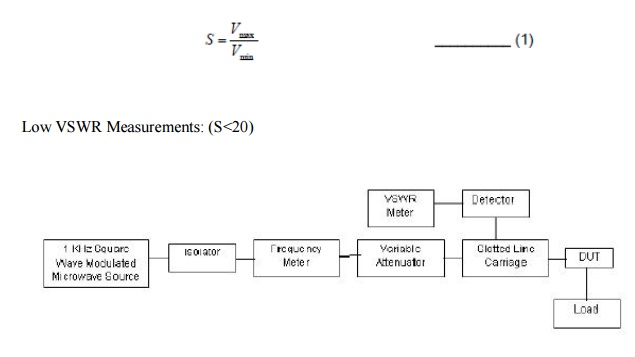
In a microwave network, if load impedance and line impedance are not matched, signal fed from the source is reflected again towards source causing standing wave pattern in the network. Voltage Standing Wave Ratio is a measure used for finding the magnitude of ration of reflected signals maximum and minimum amplitudes For analyzing standing wave pattern and to find S slotted line carriage is used in laboratory.
Procedure:
1.Microwave Source is energized with 1 KHz square wave signal as carrier.
2.Tunable passive components are so adjusted to get reading across the VSWR meter in 30 dB scale.
3.Detector (Tunable probe detector) is adjusted to get maximum power across the VSWR meter.
4. Slotted line carriage is moved from the load towards source to find the standing wave minimum position.
5.By adjusting the gain control knob of VSWR meter and attenuator the reading across the VSWR meter is made as 1 or 0 dB known as normalization.
6. Again the slotted carriage is moved towards source to find the next minimum position. The reading shown at this point in the VSWR meter is the ratio of magnitude of reflected signals minimum and maximum voltages ( ). min max VV S
7. VSWR meter has three different scales with different ranges as specified below.
a) NORMAL SWR Scale 1 ---- 1 – 4
b) NORMAL SWR Scale 2 ---- 3.2 – 10
c) EXPANDED SWR Scale 3 ---- 1 – 1.33
8.If the device under test (DUT) is having the range of VSWR 1 – 4, reading is taken from the first scale from the top (NORMAL SWR Scale 1 – 1 – 4).
9.If the device under test (DUT) is having the range of VSWR 3.2 – 10, reading is taken from the second scale from the top (NORMAL SWR Scale 2 (3.2 – 10).
10. If the device under test (DUT) is having the range of VSWR 1 – 1.33, reading is taken from the third scale from the top (EXPANDED SWR Scale 3 (1 – 1.33).
11. If the device under test (DUT) is having the range of VSWR 10 – 40, a 20 dB range is selected in the VSWR meter and reading is taken from the first scale from the top (NORMAL SWR Scale 1 – 1 – 4) which is then multiplied by 10 for getting the actual reading.
Possible Errors in Measurements:
1.Detector may not work square law region for both Vmax. and Vmin.
2.Depth of the probe in the slotted line carriage is made as minimum. If not, it may cause reflections in addition to the load reflections.
3.For the device having low VSWR, connector used for measurement must have proper matching with line impedance.
4.If the geometrical shape of the slotted line is not proper, Vmax. (or) Vmin. Value will not constant across the slotted line.
5.If the microwave signal is not properly modulated by a 1 KHz square wave, then signal becomes frequency modulated thereby it causes error in the Vmin. value measured. The value becomes lower than the actual.
6.Residual VSWR of slotted line carriage may cause error in the measurements.
High VSWR Measurements - Double Minima Method - (S>20)
Measurement of high VSWR needs separate procedure because the detector may not be tuned to work in square law region. An alternate method known as double minimum method is used for finding high VSWR with the same experimental set up as shown above.
Procedure:
1.Microwave Source is energized with 1 KHz square wave signal as carrier.
2.Tunable passive components are so adjusted to get reading across the VSWR meter in 30 dB scale.
3.Detector (Tunable probe detector) is adjusted to get maximum power across the VSWR meter.
4.Slotted line carriage is moved from the load towards source to find the standing wave minimum position. Let it be d1.
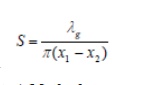
5.Slotted line carriage is moved further to find the next immediate minimum position. Let it be d2. Now
g = 2 (d1 - d2)
6.By adjusting the gain control knob of VSWR meter and attenuator the reading across the VSWR meter is made as 3 dB at this minimum position.
7.By taking this point as reference, slotted line carriage is moved on either side. The points at which the VSWR meter shows 0 dB reading on both sides are noted as x1 and x2.
8.High VSWR can be calculated by using the formula
VSWR Measurements by Return Loss (Reflectometer) Method:
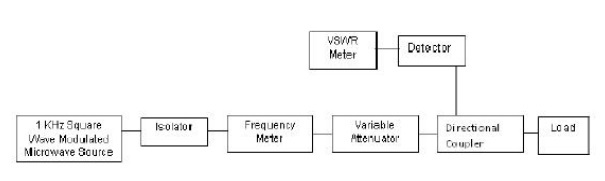
To overcome the difficulties faced in slotted line carriage for measuring VSWR, reflectometer can be used. Reflectometer is a device having two directional couplers combined together with ideal coupling factor and directivity. It is a four-port device.
Experimental Procedure:
1.Microwave Source is energized with 1 KHz square wave signal as carrier.
2.Tunable passive components are so adjusted to get reading across the VSWR meter in 30 dB scale.
3.Detector (Tunable probe detector) is adjusted to get maximum power across the VSWR meter.
4.Port 2 is with a movable short and is adjusted for getting the output across the detector to unity in VSWR meter. Port 3 is matched terminated.
5.VSWR meter and matched load at port4 and port 3 are interchanged. The output of the port3 is noted which should be ideally equal to the output from port 4.
6.Without disturbing the VSWR meter adjustment, the unknown load is connected at port 2 byreplacing the short and the output at port3 is noted to obtain
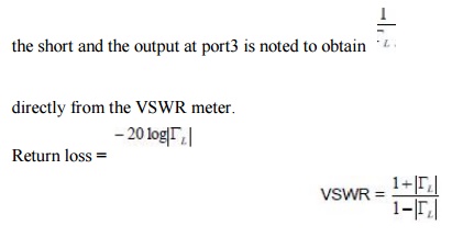
This method is well suited for loads having low VSWR. The major sources of errors are
1.Unstability of the signal source causes a change of signal power level during measurement of input and reflected signals.
2.Non-ideal directional couplers and detectors are also sources of error.
Related Topics