Chapter: Clinical Anesthesiology: Anesthetic Equipment & Monitors : The Anesthesia Machine
Problems Associated with Anesthesia Ventilators
Problems Associated with Anesthesia Ventilators
A. Ventilator–Fresh Gas Flow Coupling
From the previous discussion, it is
important to appreciate that because the ventilator’s spillvalve is closed
during inspiration, fresh gas flow from the machine’s common gas outlet
normally contrib-utes to the tidal volume delivered to the patient. For
example, if the fresh gas flow is 6 L/min, the I:E ratio is 1:2, and the
respiratory rate is 10 breaths/min, each tidal volume will include an extra 200
mL in addition to the ventilator’s output:
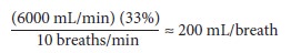
Thus, increasing fresh gas flow
increases tidal volume, minute ventilation, and peak inspiratory pressure. To
avoid problems with ventilator–fresh gas flow coupling, airway pressure and
exhaled tidal volume must be monitored closely and excessive fresh gas flows
must be avoided.
B. Excessive Positive Pressure
Intermittent or sustained high
inspiratory pressures (>30 mm Hg) during positive-pressure ventilation
increase the risk of pulmonary barotrauma (eg, pneumothorax) or hemodynamic
compromise, or both, during anesthesia. Excessively high pressures may arise
from incorrect settings on the ventilator, ventilator malfunction, fresh gas
flow coupling (above), or activation of the oxygen flush during the inspiratory
phase of the ventilator. Use of the oxygen flush valve during the inspiratory
cycleof a ventilator must be avoided
because the ventilator spill valve will be closed and the APL valve is
excluded; the surge of oxygen (600–1200 mL/s) and circuit pressure will be
transferred to the patient’s lungs.
In addition to a high-pressure alarm,
all venti-lators have a built-in automatic or APL valve. The mechanism of
pressure limiting may be as simple as a threshold valve that opens at a certain
pressure or electronic sensing that abruptly terminates the ven-tilator
inspiratory phase.
C. Tidal Volume Discrepancies
Large discrepancies between the set and actual tidal volume that the patient receives are oftenobserved in the operating room during volume con-trol ventilation. Causes include breathing-circuit compliance, gas compression, ventilator–fresh gas flow coupling (above), and leaks in the anesthe-sia machine, the breathing circuit, or the patient’s airway.The compliance for standard adult breath-ing circuits is about 5 mL/cm H2O. Thus, if peak inspiratory pressure is 20 cm H2O, about 100 mL of set tidal volume is lost to expanding the circuit. For this reason breathing circuits for pediatric patients are designed to be much stiffer, with compliances as small as 1.5–2.5 mL/cm H2O.
Compression
losses, normally about 3%, are due to gas compression within the ventilator
bellows and may be dependent on breathing-circuit volume. Thus if tidal volume is 500 mL another 15 mL of the set
tidal gas may be lost. Gas sampling for capnog-raphy and anesthetic gas
measurements represent additional losses in the form of gas leaks unless the
sampled gas is returned to the breathing circuit, as occurs in some machines.
Accurate detection of tidal volume
discrepan-cies is dependent on where the spirometer is placed. Sophisticated
ventilators measure both inspira-tory and expiratory tidal volumes. It is
important to note that unless the spirometer is placed at the Y-connector in
the breathing circuit, compliance and compression losses will not be apparent.
Several mechanisms have been built into
newer anesthesia machines to reduce tidal volume discrep-ancies. During the
initial electronic self-checkout, some machines measure total system compliance
and subsequently use this measurement to adjust the excursion of the ventilator
bellows or piston; leaks may also be measured but are usually not compensated.
The actual method of tidal volume compensation or modulation varies according
to manufacturer and model. In one design a flow sensor measures the tidal
volume delivered at the inspiratory valve for the first few breaths and adjusts
subsequent metered drive gas flow volumes to compensate for tidal volume losses
(feedback adjustment). Another design continually measures fresh gas and
vaporizer flow and subtracts this amount from the metered drive gas flow
(pre-emptive adjustment). Alternately, machines that use electronic control of
gas flow can decouple fresh gas flow from the tidal volume by delivery of fresh
gas flow only during exhalation. Lastly, the inspiratory phase of the
ventilator–fresh gas flow may be diverted through a decoupling valve into the
breathing bag, which is excluded from the circle system during venti-lation.
During exhalation the decoupling valve opens, allowing the fresh gas that was
temporarily stored in the bag to enter the breathing circuit.
Related Topics