Chapter: Clinical Anesthesiology: Anesthetic Equipment & Monitors : The Anesthesia Machine
Anesthesia Flow Control Circuits
FLOW CONTROL CIRCUITS
Pressure Regulators
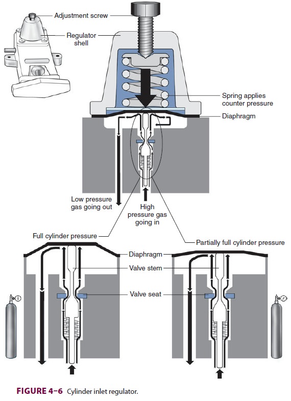
Unlike the relatively constant pressure
of the pipe-line gas supply, the high and variable gas pres-sure in cylinders
makes flow control difficult and potentially dangerous. To enhance safety and
ensure optimal use of cylinder gases, machines uti-lize a pressure regulator to
reduce the cylinder gas pressure to 45–47 psig1
before it enters the flow valve (Figure 4–6). This pressure, which is slightly
lower than the pipeline supply, allows preferential use of the pipeline supply
if a cylinder is left open (unless pipeline pressure drops below 45 psig).
After pass-ing through Bourdon pressure gauges and check valves, the pipeline
gases share a common pathway with the cylinder gases. A high-pressure relief
valve provided for each gas is set to open when the sup-ply pressure exceeds
the machine’s maximum safety limit (95–110 psig), as might happen with a
regula-tor failure on a cylinder. Some machines also use a second regulator to
drop both pipeline and cylinder pressure further (two-stage pressure
regulation). A second-stage pressure reduction may also be needed for an
auxiliary oxygen flowmeter, the oxygen flush mechanism, or the drive gas to
power a pneumatic ventilator.
Oxygen Supply
Failure Protection Devices
Whereas the oxygen supply can pass
directly to its flow control valve, nitrous oxide, air (in somemachines), and
other gases must first pass through safety devices before reaching their
respective flow control valves. In other machines, air passes directly to its
flow control valve; this allows administration of air even in the absence of
oxygen. These devices per-mit the flow of other gases only if there is
sufficient oxygen pressure in the safety device and help prevent accidental
delivery of a hypoxic mixture in the event of oxygen supply failure. Thus in
addition to supply-ing the oxygen flow control valve, oxygen from the common
inlet pathway is used to pressurize safety devices, oxygen flush valves, and
ventilator power outlets (in some models). Safety devices sense oxygen pressure
via a small “piloting pressure” line that may be derived from the gas inlet or
secondary regula-tor. In some anesthesia machine designs (eg, Datex-Ohmeda
Excel), if the piloting pressure line falls below a threshold (eg, 20 psig),
the shut-off valves close, preventing the administration of any other gases.
The terms fail-safe and nitrous cut-off were pre-viously used
for the nitrous oxide shut-off valve.
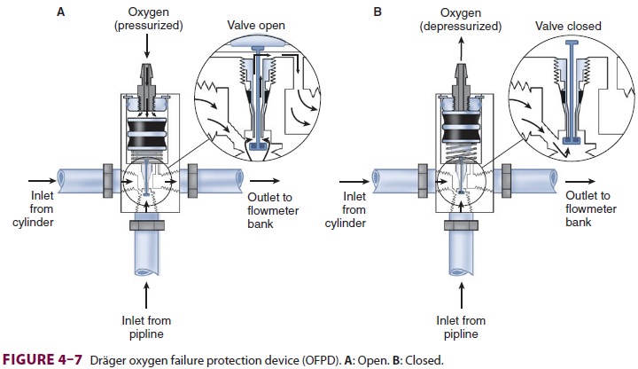
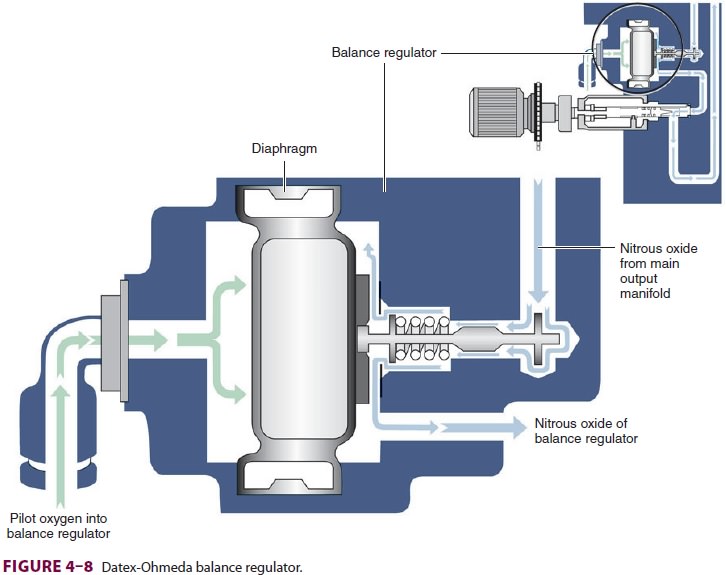
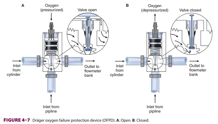
Most modern (particularly Datex-Ohmeda)
machines use a proportioning safety device instead of a threshold shut-off
valve. These devices, called either an oxygen failure protection device
(Dräger) or a balance regulator (Datex-Ohmeda), propor-tionately reduce the
pressure of nitrous oxide and other gases except for air (Figures 4–7 and 4–8).
They completely shut off nitrous oxide and other gas flow only below a set
minimum oxygen pressure (eg, 0.5 psig for nitrous oxide and 10 psig for other
gases).
All machines also have an oxygen supply
low-pressure sensor that activates alarm sounds when inlet gas pressure drops
below a threshold value (usu-ally 20–30 psig). It must be emphasized that these
safety devices do not protect against
other possible causes of hypoxic accidents (eg, gas line misconnec-tions), in
which threshold pressure may be main-tained by gases containing inadequate or
no oxygen.
Flow Valves & Meters
Once the pressure has been reduced to a
safe level, each gas must pass through flow control valves and is measured by
flowmeters before mixing with other gases, entering the active vaporizer, and
exiting the machine’s common gas outlet. Gas
lines proximalto flow valves are considered to be in the high-pressure circuit
whereas those between the flow valves and the common gas outlet are considered
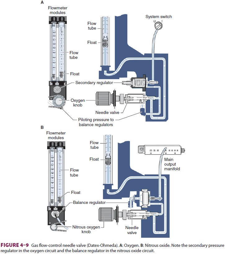
part of the low-pressure circuit of the machine. When the knob of the flow
control valve is turned counterclockwise, a needle valve is disengaged from its
seat, allowing gas to flow through the valve (Figure 4–9). Stops in the
full-off and full-on posi-tions prevent valve damage. Touch- and color-coded
control knobs make it more difficult to turn the wrong gas off or on. As a
safety feature the oxygen knob is usually fluted, larger, and protrudes farther
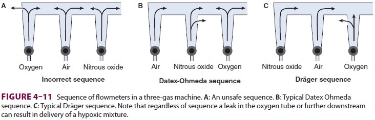
than the other knobs. The oxygen flowmeter is positioned furthest to the right,
downstream to the other gases; this arrangement helps to prevent hypoxia if
there is leakage from a flowmeter positioned upstream.
Flow control knobs control gas entry
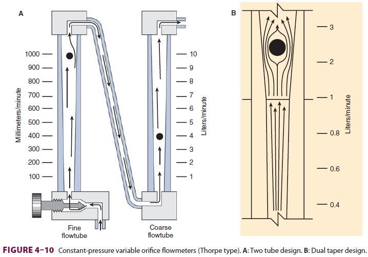
into the flowmeters by adjustment via a needle valve. Flowmeters on anesthesia
machines are classified as either constant-pressure variable-orifice
(rotameter) or electronic. In constant-pressure variable-orifice flowmeters, an
indicator ball, bobbin, or float is sup-ported by the flow of gas through a
tube (Thorpe
tube) whose bore (orifice) is tapered.
Near the bot-tom of the tube, where the diameter is small, a low flow of gas
will create sufficient pressure under the float to raise it in the tube. As the
float rises, the (variable) orifice of the tube widens, allowing more gas to
pass around the float. The float will stop rising when its weight is just
supported by the difference in pressure above and below it. If flow is
increased, the pressure under the float increases, raising it higher in the
tube until the pressure drop again just sup-ports the float’s weight. This
pressure drop is con-stant regardless of the flow rate or the position in the
tube and depends on the float weight and tube cross-sectional area.
Flowmeters are calibrated for specific
gases, as the flow rate across a constriction depends on the gas’s viscosity at
low laminar flows (Poiseuille’s law) and its density at high turbulent flows.
To minimize the effect of friction between them and the tube’s wall, floats are
designed to rotate constantly, which keeps them centered in the tube. Coating
the tube’s interior with a conductive substance grounds the system and reduces
the effect of static electricity. Some flowmeters have two glass tubes, one for
low flows and another for high flows (Figure 4–10A); the two tubes are in series and
are still controlled by one valve. A dual taper design can allow a sin-gle
flowmeter to read both high and low flows (Figure 4–10B). Causes of flowmeter malfunctioninclude debris in the flow tube,
vertical tube mis-alignment, and sticking or concealment of a float at the top
of a tube.
Should a leak develop within or
downstream from an oxygen flowmeter, a hypoxic gas mixture can be delivered to
the patient (Figure
4–11). To reduce this risk, oxygen flowmeters are always posi-tioned downstream to all
other flowmeters (nearest to the vaporizer).
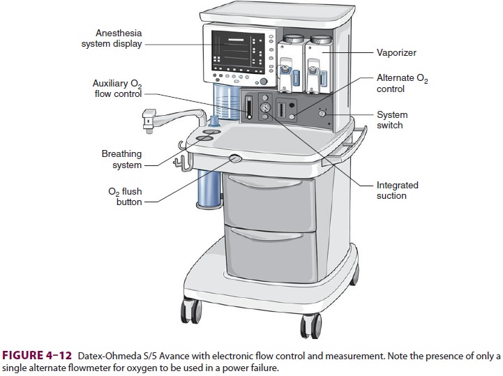
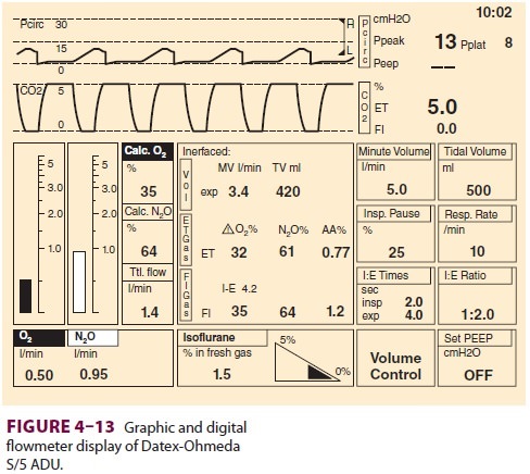
Some anesthesia machines have electronic
flow control and measurement (Figure 4–12). In such instances, a back-up
conventional (Thorpe) auxil-iary oxygen flowmeter is provided. Other models
have conventional flowmeters but electronic mea-surement of gas flow along with
Thorpe tubes and
digital or digital/graphic displays ( Figure 4–13).
The amount of pressure drop caused by a flow restrictor is the basis for
measurement of gas flow rate in these systems. In these machines oxygen,
nitrous oxide, and air each have a separate electronic flow mea-surement device
in the flow control section before they are mixed together. Electronic
flowmeters are essential components in workstations if gas flow rate data will
be acquired automatically by computerized anesthesia recording systems.
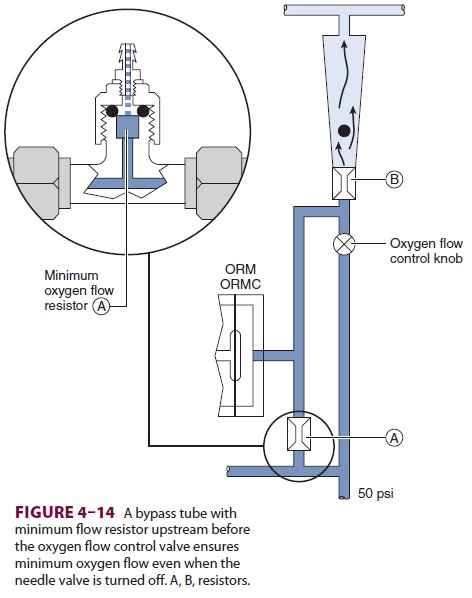
A. Minimum Oxygen Flow
The oxygen flow valves are usually
designed to deliver a minimum flow of 150 mL/min when the anesthe-sia machine
is turned on. One method involves the use of a minimum flow resistor (Figure 4–14).
This safety feature helps ensure that some oxygen enters the breathing circuit
even if the operator forgets to turn on the oxygen flow. Some machines are
designed to deliver minimum flow or low-flow anes-thesia (<1 L/min) and have minimum oxygen flows as low as 50
mL/min.
B. Oxygen/Nitrous Oxide Ratio Controller
Another safety feature of anesthesia machines is a linkage of the nitrous oxide gas flow to theoxygen gas flow; this arrangement helps ensure a minimum oxygen concentration of 25%. The oxy-gen/nitrous oxide ratio controller links the two flow valves either pneumatically or mechanically. To maintain the minimum oxygen concentration, the system (Link-25) in Datex-Ohmeda machines increases the flow of oxygen, whereas the oxy-gen ratio monitor controller (ORMC) in Dräger machines reduces the concentration of nitrous oxide. It should be noted that this safety device does not affect the flow of a third gas (eg, air, helium, or carbon dioxide).
Vaporizers
Volatile anesthetics (eg, halothane,
isoflurane, des-flurane, sevoflurane) must be vaporized before being delivered
to the patient. Vaporizers have concen-tration-calibrated dials that precisely
add volatile anesthetic agents to the combined gas flow from all flowmeters.
They must be located between the flow-meters and the common gas outlet.
Moreover, unless the machine accepts only one vaporizer at a time, all
anesthesia machines should have an interlocking or exclusion device that
prevents the concurrent use of more than one vaporizer.
A. Physics of Vaporization
At temperatures encountered in the
operating room, the molecules of a volatile anesthetic in a closed con-tainer
are distributed between the liquid and gaseous phases. The gas molecules
bombard the walls of the container, creating the saturated vapor pressure of
that agent. Vapor pressure depends on the character-istics of the volatile
agent and the temperature. The greater the temperature, the greater the
tendency for the liquid molecules to escape into the gaseous phase and the
greater the vapor pressure (Figure 4–15). Vaporization requires energy
(the latent heat of vaporization), which results in a loss of heat from the
liquid. As vaporization proceeds, temperature of the remaining liquid
anesthetic drops and vapor pres-sure decreases unless heat is readily available
to enter the system. Vaporizers contain a chamber in which a carrier gas
becomes saturated with the volatile agent.
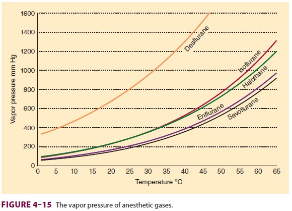
A liquid’s boiling point is the
temperature at which its vapor pressure is equal to the atmospheric pressure.
As the atmospheric pressure decreases (as in higher altitudes), the boiling
point also decreases. Anesthetic agents with low boiling points are more
susceptible to variations in barometric pressure than agents with higher
boiling points. Among the com-monly used agents, desflurane has the lowest
boiling point (22.8°C at 760 mm Hg).
B. Copper Kettle
The copper kettle vaporizer is no longer
used in clini-cal anesthesia; however, understanding how it works provides
invaluable insight into the delivery of vola-tile anesthetics ( Figure 4–16).
It is classified as a measured-flow vaporizer (or flowmeter-controlled
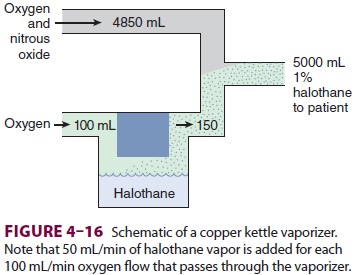
vaporizer). In a copper kettle, the
amount of carrier gas bubbled through the volatile anesthetic is con-trolled by
a dedicated flowmeter. This valve is turned off when the vaporizer circuit is
not in use. Copper is used as the construction metal because its relatively
high specific heat (the quantity of heat required to raise the temperature of 1
g of substance by 1°C) and high thermal conductivity (the speed of heat
con-ductance through a substance) enhance the vapor-izer’s ability to maintain
a constant temperature. All the gas entering the vaporizer passes through the
anesthetic liquid and becomes saturated with vapor. One milliliter of liquid
anesthetic is the equivalent of approximately 200 mL of anesthetic vapor.
Because the vapor pressure of volatile anesthetics is greater than the partial
pressure required for anesthesia, the saturated gas leaving a copper kettle has
to be diluted before it reaches the patient.
For example, the vapor pressure of
halothane is 243 mm Hg at 20°C, so the concentration of halo-thane exiting a
copper kettle at 1 atmosphere would be 243/760, or 32%. If 100 mL of oxygen
enters the kettle, roughly 150 mL of gas exits (the initial 100 mL of oxygen
plus 50 mL of saturated halo-thane vapor), one-third of which would be
saturated halothane vapor. To deliver a 1% concentration of halothane (MAC
0.75%), the 50 mL of halothane vapor and 100 mL of carrier gas that left the
copper kettle have to be diluted within a total of 5000 mL of fresh gas flow.
Thus, every 100 mL of oxygen passing through a halothane vaporizer translates
into a 1% increase in concentration if total gas flow into the breathing
circuit is 5 L/min. Therefore when total flow is fixed, flow through the
vaporizer determines the ultimate concentration of anesthetic. Isoflurane has
an almost identical vapor pressure, so the same relationship between copper
kettle flow, total gas flow, and anesthetic concentration exists. However, if
total gas flow changes without an adjustment in copper kettle flow (eg,
exhaustion of a nitrous oxide cylinder), the delivered volatile anesthetic
concen-tration rises rapidly to potentially dangerous levels.
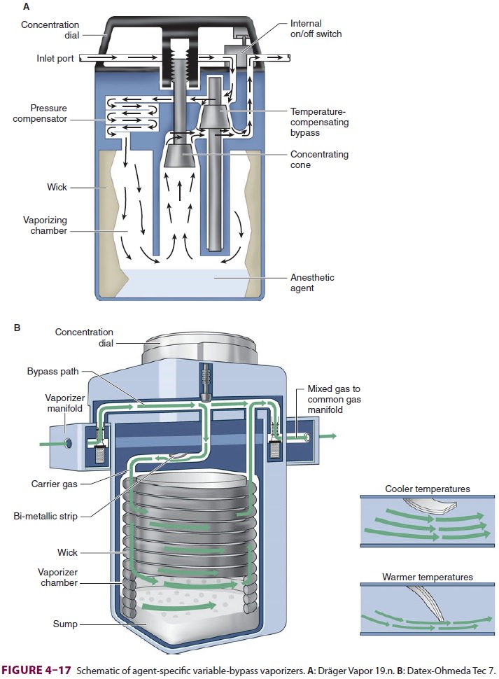
C. Modern Conventional Vaporizers
All modern vaporizers are agent specific
and temperature corrected, capable of deliver-ing a constant concentration of
agent regardless of temperature changes or flow through the vaporizer. Turning
a single calibrated control knob counter-clockwise to the desired percentage
diverts an appropriate small fraction of the total gas flow into the carrier
gas, which flows over the liquid anes-thetic in a vaporizing chamber, leaving
the balance to exit the vaporizer unchanged (Figure 4–17). Because some of
the entering gas is never exposed to anesthetic liquid, this type of
agent-specific vapor-izer is also known as a variable-bypass vaporizer.
Temperature compensation is achieved by
a strip composed of two different metals welded together. The metal strips
expand and contract dif-ferently in response to temperature changes. When the
temperature decreases, differential contraction causes the strip to bend
allowing more gas to pass through the vaporizer. Such bimetallic strips are
also used in home thermostats. As the temperature rises differential expansion
causes the strip to bend the other way restricting gas flow into the vaporizer.
Altering total fresh gas flow rates within a wide range does not significantly
affect anesthetic concentration because the same proportion of gas is exposed
to the liquid. However, the real output of an agent would be lower than the
dial setting at extremely high flow (>15 L/min); the converse is true when
the flow rate is less than 250 mL/min. Changing the gas composi-tion from 100%
oxygen to 70% nitrous oxide may transiently decrease volatile anesthetic
concentra-tion due to the greater solubility of nitrous oxide in volatile
agents.
Given that these vaporizers are agent
specific, filling them with the incorrect anesthetic should be avoided. For
example, unintentionally filling a sevoflurane-specific vaporizer with
halothane could lead to an anesthetic overdose. First, halothane’s higher vapor
pressure (243 mm Hg versus 157 mm Hg) will cause a 40% greater amount of
anesthetic vapor to be released. Second, halothane is more than twice as potent
as sevoflurane (MAC 0.75 versus. 2.0). Conversely, filling a halothane
vaporizer with sevoflurane will cause an anesthetic underdosage. Modern
vaporizers offer agent-specific keyed filling ports to prevent filling with an
incorrect agent.
Excessive tilting of older vaporizers
(Tec 4, Tec 5, and Vapor 19.n) during transport may flood the bypass area and
lead to dangerously high anesthetic concentrations. In the event of tilting and
spill-age, high flow of oxygen with the vaporizer turned off should be used to
vaporize and flush the liquid anesthetic from the bypass area. Fluctuations in
pressure from positive-pressure ventilation in older anesthesia machines may
cause a transient reversal of flow through the vaporizer, unpredictably
chang-ing agent delivery. This “pumping effect” is more pronounced with low gas
flows. A one-way check valve between the vaporizers and the oxygen flush valve
(Datex-Ohmeda) together with some design modifications in newer units limit the
occurrence of some of these problems. Variable bypass vapor-izers compensate
for changes in ambient pressures (ie, altitude changes maintaining relative
anesthetic gas partial pressure).
D. Electronic Vaporizers
Electronically controlled vaporizers
must be utilized for desflurane and are used for all volatile anesthet-ics in
some sophisticated anesthesia machines.
1.
Desflurane vaporizer—Desflurane’s
vapor pres-sure is so high that at sea level it almost boils at room
temperature (Figure 4–15). This high vola-tility, coupled with a potency only
one-fifth that of other volatile agents, presents unique delivery problems.
First, the vaporization required for gen-eral anesthesia produces a cooling
effect that would overwhelm the ability of conventional vaporizers to maintain
a constant temperature. Second, because it vaporizes so extensively, a
tremendously high fresh gas flow would be necessary to dilute the carrier gasto
clinically relevant concentrations. These problems have been addressed by the
development of special desflurane vaporizers. A reservoir containing
desflu-rane (desflurane sump) is electrically heated to 39°C (significantly
higher than its boiling point) creating a vapor pressure of 2 atmospheres.
Unlike a variable-bypass vaporizer, no fresh gas flows through the des-flurane
sump. Rather, pure desflurane vapor joins the fresh gas mixture before exiting
the vaporizer. The amount of desflurane vapor released from the sump depends on
the concentration selected by turning the control dial and the fresh gas flow
rate. Although the Tec 6 Plus maintains a constant desflurane con-centration
over a wide range of fresh gas flow rates, it cannot automatically compensate for
changes in elevation. Decreased ambient pressure (eg, high elevation) does not
affect the concentration of agent delivered, but decreases the partial pressure
of the agent. Thus, at high elevations, the anesthesiologist must manually
increase the concentration control.
2.
Aladin cassette vaporizer—This
vaporizer isdesigned for use with the Datex-Ohmeda S/5 ADU and Aisys machines.
Gas flow from the flow con-trol is divided into bypass flow and liquid chamber
flow (Figure
4–18). The latter is conducted into an agent-specific, color-coded,
cassette (Aladin cassette) in which the volatile anesthetic is vaporized. The
machine accepts only one cassette at a time and rec-ognizes the cassette
through magnetic labeling. The cassette does not contain any bypass flow
channels; therefore, unlike traditional vaporizers, liquid anes-thetic cannot
escape during handling and the cassette can be carried in any position. After
leaving the cas-sette, the now anesthetic-saturated liquid chamber flow
reunites with the bypass flow before exiting the fresh gas outlet. A flow
restrictor valve near the bypass flow helps to adjust the amount of fresh gas
that flows to the cassette. Adjusting the ratio between the bypass flow and
liquid chamber flow changes the concentration of volatile anesthetic agent
delivered to the patient. In practice, the clinician changes the con-centration
by turning the agent wheel, which oper-ates a digital potentiometer. Software
sets the desired fresh gas agent concentration according to the num-ber of output
pulses from the agent wheel. Sensors in the cassette measure pressure and
temperature, thus determining agent concentration in the gas leaving the
cassette. Correct liquid chamber flow is
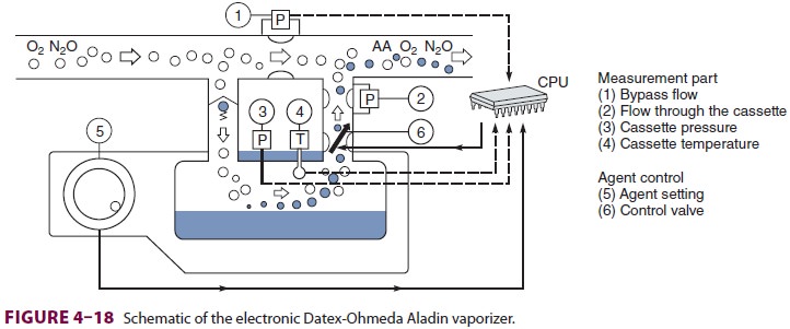
calculated based on desired fresh gas
concentration and determined cassette gas concentration.
Common (Fresh) Gas Outlet
In contrast to the multiple gas inlets,
the anesthesia machine has only one common gas outlet that sup-plies gas to the
breathing circuit. The term fresh gasoutlet
is also of ten used because of its critical rolein adding new gas of fixed
and known composi-tion to the circle system. Unlike older models, some newer
anesthesia machines measure and report common outlet gas flows (Datex-Ohmeda
S/5 ADU and Narkomed 6400). An antidisconnect retaining device is used to
prevent accidental detachment of the gas outlet hose that connects the machine
to the breathing circuit.
The oxygen flush valve provides a high
flow (35–75 L/min) of oxygen directly to the common gas outlet, bypassing the
flowmeters and vaporizers. It is used to rapidly refill or flush the breathing
circuit, but because the oxygen may be supplied at a line pres-sure of 45–55
psig, there is a real potential of lung barotrauma. For this reason, the flush
valve must be used cautiously whenever a patient is connected to the breathing
circuit. Moreover, inappropriate use of the flush valve (or a situation of
stuck valve) may result in backflow of gases into the low-pressure cir-cuit,
causing dilution of inhaled anesthetic concen-tration. Some machines use a
second-stage regulator to drop the oxygen flush pressure to a lower level.
A protective rim around the flush button
limits the possibility of unintentional activation. Anesthesia machines (eg,
Datex-Ohmeda Aestiva/5) may have an optional auxiliary common gas outlet that
is acti-vated with a dedicated switch. It is primarily used for performing the
low-pressure circuit leak test (see Anesthesia Machine Checkout List).
Related Topics