Chapter: Clinical Anesthesiology: Anesthetic Equipment & Monitors : The Anesthesia Machine
Anesthesia Ventilator Circuit Design

Ventilator Circuit Design
Traditionally ventilators
on anesthesia machines have a
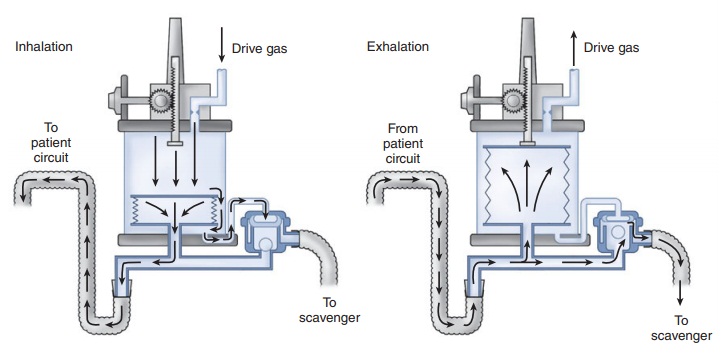
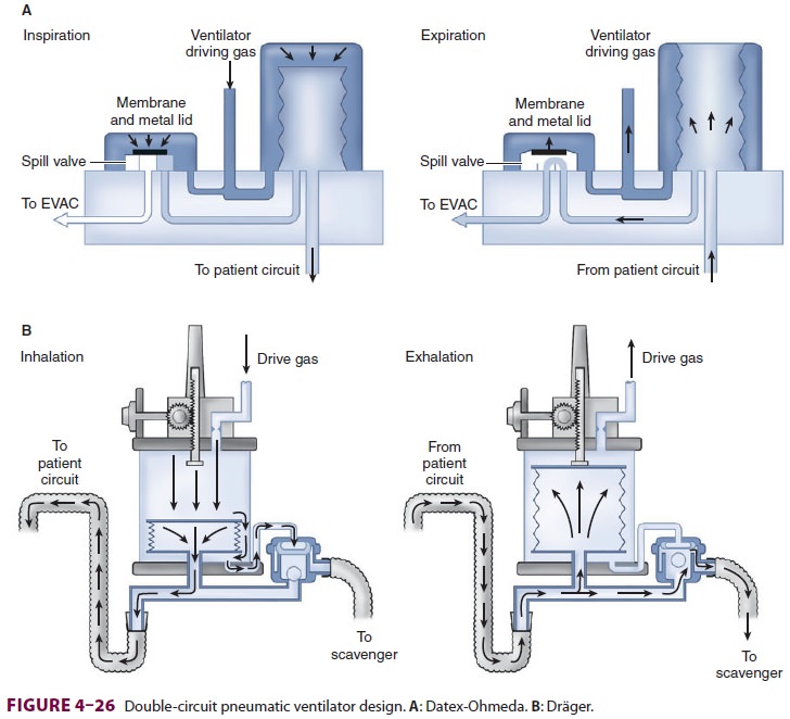
double-circuit system design and are pneumatically powered and
electronicallycontrolled (Figure 4–26). Newer machines also incorporate
microprocessor control that relies on sophisticated pressure and flow sensors.
This feature allows multiple ventilatory modes, electronic PEEP, tidal volume
modulation, and enhanced safety

features. Some anesthesia machines have
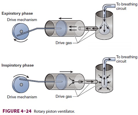
ventilators that use a single-circuit piston design (Figure 4–24).

A. Double-Circuit System Ventilators
In a double-circuit system design, tidal
volume is delivered from a bellows assembly that con-sists of a bellows in a
clear rigid plastic enclosure (Figure 4–26). A standing (ascending) bellows is
preferred as it readily draws attention to a circuit disconnection by
collapsing. Hanging (descending) bellows are rarely used and must not be
weighted;
A: Datex-Ohmeda. B: Dräger.older ventilators with weighted hanging bellows continue
to fill by gravity despite a disconnection in the breathing circuit.
The bellows in a double-circuit design
ventila-tor takes the place of the breathing bag in the anes-thesia circuit.
Pressurized oxygen or air from the ventilator power outlet (45–50 psig) is
routed to the space between the inside wall of the plastic enclosure and the
outside wall of the bellows. Pressurization of the plastic enclosure compresses
the pleated bel-lows inside, forcing the gas inside into the breathingcircuit
and patient. In contrast, during exhalation, the bellows ascend as pressure
inside the plastic enclosure drops and the bellows fill up with the exhaled
gas. A ventilator flow control valve regu-lates drive gas flow into the
pressurizing chamber. This valve is controlled by ventilator settings in the
control box (Figure 4–26). Ventilators with micro-processors also utilize
feedback from flow and pres-sure sensors. If oxygen is used for pneumatic power
it will be consumed at a rate at least equal to minute ventilation. Thus, if
oxygen fresh gas flow is 2 L/min and a ventilator is delivering 6 L/min to the
circuit, a total of at least 8 L/min of oxygen is being con-sumed. This should
be kept in mind if the hospi-tal’s medical gas system fails and cylinder oxygen
is required. Some anesthesia machines reduce oxygen consumption by
incorporating a Venturi device that draws in room air to provide air/oxygen
pneumatic power. Newer machines may offer the option of using compressed air
for pneumatic power. A leak in the ventilator bellows can transmit high gas
pres-sure to the patient’s airway, potentially resulting in pulmonary
barotrauma. This may be indicated by
ahigher than expected rise in inspired oxygen con-centration (if oxygen is the
sole pressurizing gas). Some machine ventilators have a built-in drive gas
regulator that reduces the drive pressure (eg, to 25 psig) for added safety.
Double-circuit design ventilators also
incor-porate a free breathing valve that allows outside air to enter the rigid
drive chamber and the bellows to collapse if the patient generates negative
pressure by taking spontaneous breaths during mechanical ventilation.
B. Piston Ventilators
In a piston design, the ventilator
substitutes an elec-trically driven piston for the bellows (Figure 4–24); the
ventilator requires either minimal or no pneumatic (oxygen) power. The major
advantage of a piston ventilator is its ability to deliver accurate tidal
volumes to patients with very poor lung compliance and to very small patients.
During volume-controlled ventilation the piston moves at a constant velocity
whereas during pressure-controlled ventilation the piston moves with decreasing
velocity. As with the bellows, the piston fills with gas from the breathing
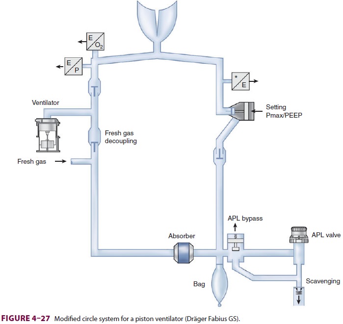
circuit. To prevent generation of significant negative pressure during the
downstroke of the piston the circle system configura-tion has to be modified (Figure 4–27).
The ventilator must also incorporate a negative-pressure relief valve or be
capable of terminating the piston’s downstroke if negative pressure is
detected. Introduction of a negative-pressure relief valve to the breathing
circuit may introduce the risk of air entrainment and the potential for
dilution of oxygen and volatile anes-thetic concentrations if the patient
breathes during mechanical ventilation and low fresh gas flows.

C. Spill Valve
Whenever a ventilator is used on an
anesthesia machine, the circle system’s APL valve must be functionally removed
or isolated from the circuit. A bag/ventilator switch typically accomplishes
this. When the switch is turned to “bag” the ventilator is excluded and
spontaneous/manual (bag) ventila-tion is possible. When it is turned to
“ventilator,” the breathing bag and the APL are excluded from the breathing
circuit. The APL valve may be automati-cally excluded in some newer anesthesia
machines when the ventilator is turned on. The ventilator con-tains its own
pressure-relief (pop-off ) valve, called the spill valve, which is
pneumatically closed during inspiration so that positive pressure can be
gener-ated (Figure 4–26). During exhalation, the pressur-izing gas is vented
out and the ventilator spill valve is no longer closed. The ventilator bellows
or piston refill during expiration; when the bellows is com-pletely filled, the
increase in circle system pressure causes the excess gas to be directed to the
scavenging system through the spill valve. Sticking of this valve can result in
abnormally elevated airway pressure during exhalation.
Related Topics