Chapter: Clinical Anesthesiology: Anesthetic Equipment & Monitors : The Anesthesia Machine
Anesthesia Ventilators

VENTILATORS
Ventilators are used extensively in the
operating room (OR) and the intensive care unit (ICU). All modern anesthesia
machines are equipped with a ventilator. Historically OR ventilators were
simpler and more compact than their ICU counterparts. This distinction has
become blurred due to advances in technology together with an increasing need
for “ICU-type” ventilators as more critically ill patients come to the OR. The
ventilators on some modern machines are just as sophisticated as those in the
ICU and have almost the same capabilities. After a general discussion of basic
ventilator principles, this section reviews the use of ventilators in
conjunction with anesthesia machines.
Overview
Ventilators generate gas flow by
creating a pres-sure gradient between the proximal airway and the alveoli.
Older units relied on the generation of nega-tive pressure around (and inside)
the chest (eg, iron lungs), whereas modern ventilators generate posi-tive
pressure and gas flow in the upper airway.
Ventilator function is best described in rela-tion to the four phases of the ventilatory cycle: inspiration, the transition from inspiration to expiration, expiration, and the transition from expiration to inspiration. Although several clas-sification schemes exist, the most common is based on inspiratory phase characteristics and the method of cycling from inspiration to expiration.
Other classification categories may
include power source (eg, pneumatic-high pressure, pneumatic-Venturi, or
electric), design (single-circuit system, double-circuit system, rotary piston,
linear piston), and control mechanisms (eg, electronic timer or
microprocessor).
A. Inspiratory Phase
During inspiration, ventilators generate
tidal volumes by producing gas flow along a pressure gradient. The machine
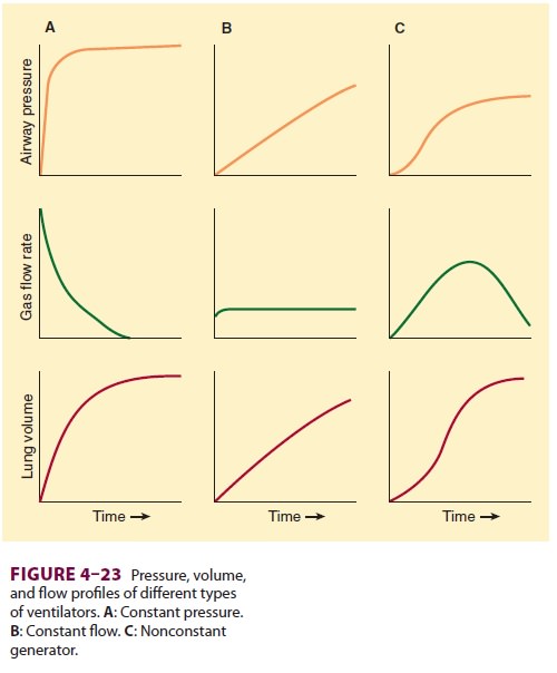
generates either a con-stant pressure (constant-pressure generators) or
constant gas flow rate (constant-flow generators) during inspiration,
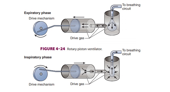
regardless of changes in lung mechanics ( Figure 4–23). Nonconstant generators produce
pressures or gas flow rates that vary dur-ing the cycle but remain consistent
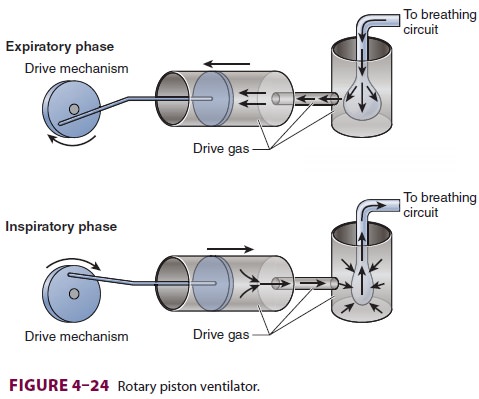
from breath to breath. For instance, a ventilator that generates a flow pattern
resembling a half cycle of a sine wave (eg, rotary piston ventilator) would be
classified as a nonconstant-flow generator. An increase in airway resistance or
a decrease in lung compliance would increase peak inspiratory pressure but
would not alter the flow rate generated by this type of ventila-tor (Figure 4–24).


B. Transition Phase from Inspiration to Expiration
Termination of the inspiratory phase can be trig-gered by a preset limit of time (fixed duration), a set inspiratory pressure that must be reached, or a predetermined tidal volume that must be deliv-ered. Time-cycled ventilators allow tidal volume and peak inspiratory pressure to vary depend-ing on lung compliance. Tidal volume is adjusted by setting inspiratory duration and inspiratory flow rate. Pressure-cycled ventilators will not cycle from the inspiratory phase to the expiratory phase until a preset pressure is reached. If a large circuit leak decreases peak pressures significantly, pressure-cycled ventilator may remain in the inspiratory phase indefinitely. On the other hand,small leak may not markedly decrease tidal vol-ume, because cycling will be delayed until the pressure limit is met. Volume-cycled ventilators vary inspiratory duration and pressure to deliver a preset volume. In reality, modern ventilators over-come the many shortcomings of classic ventilator designs by incorporating secondary cycling param-eters or other limiting mechanisms. For example, time-cycled and volume-cycled ventilators usu-ally incorporate a pressure-limiting feature that terminates inspiration when a preset, adjustable safety pressure limit is reached. Similarly a volume-preset control that limits the excursion of the bel-lows allows a time-cycled ventilator to function somewhat like a volume-cycled ventilator, depend-ing on the selected ventilator rate and inspiratory flow rate.
C. Expiratory Phase
The expiratory phase of ventilators
normally reduces airway pressure to atmospheric levels or some preset value of
positive end-expiratory pressure (PEEP). Exhalation is therefore passive. Flow
out of the lungs is determined primarily by airway resistance and lung compliance.
Expired gases fill up the bellows; hey are then relieved to the scavenging
system. PEEP is usually created with an adjustable spring valve mechanism or
pneumatic pressurization of the exhalation (spill) valve.
D. Transition Phase from Expiration to Inspiration
Transition into the next inspiratory
phase may be based on a preset time interval or a change in pressure. The
behavior of the ventilator during this phase together with the type of cycling
from inspi-ration to expiration determines ventilator mode.During controlled
ventilation, the most basic mode of all ventilators, the next breath always
occurs after a preset time interval. Thus tidal vol-ume and rate are fixed in
volume-controlled ven-tilation, whereas peak inspiratory pressure is fixed in
pressure-controlled ventilation. Controlled ventilation modes are not designed
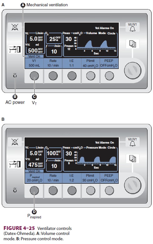
for spontane-ous breathing. In the volume-control mode, the ventilator adjusts
gas flow rate and inspiratory time based on the set ventilatory rate and I:E
ratio (Figure
4–25A). In the pressure-control mode, inspiratory time is also based
on the set ventilator rate and inspiratory-to-expiratory (I:E) ratio, but gas
flow is adjusted to maintain a constant inspira-tory pressure (Figure 4–25B).

In contrast, intermittent mandatory
ventila-tion (IMV) allows patients to breathe spontaneously between controlled
breaths. Synchronized inter-mittent mandatory ventilation (SIMV) is a further
refinement that helps prevent “fighting the ventila-tor” and “breath stacking”;
whenever possible, the ventilator tries to time the mandatory mechanical
breaths with the drops in airway pressure below the end-expiratory pressure
that occur as the patient ini-tiates a spontaneous breath.
Related Topics