Chapter: Clinical Anesthesiology: Anesthetic Equipment & Monitors : The Anesthesia Machine
Anesthesia The Breathing Circuit
THE BREATHING CIRCUIT
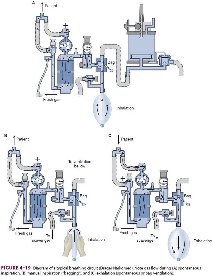
The breathing system most commonly used
with anesthesia machines is the circle system (Figure 4–19); a Bain circuit is
occasionally used. The components and use of the circle system were previously
discussed. It is important to note that gas composition at the common gas outlet
can be controlled precisely and rapidly by adjustments in flowmeters and
vaporizers. In contrast, gas com-position, especially volatile anesthetic
concentra-tion, in the breathing circuit is significantly affected by other
factors, including anesthetic uptake in the patient’s lungs, minute
ventilation, total fresh gas flow, volume of the breathing circuit, and the
pres-ence of gas leaks. Use of high gas flow rates during induction and
emergence decreases the effects of such variables and can diminish the
magnitude of discrepancies between fresh gas outlet and circle system
anesthetic concentrations. Measurement of inspired and expired anesthetic gas
concentration also greatly facilitates anesthetic management.
In
most machines the common gas outlet is attached to the breathing circuit just
past the exhala-tion valve to prevent artificially high exhaled tidal volume
measurements. When spirometry measure-ments are made at the Y-connector, fresh
gas flow can enter the circuit on the patient side of the inspiratory valve.
The latter enhances CO2 elimination and may help reduce desiccation
of the CO2 absorbent.
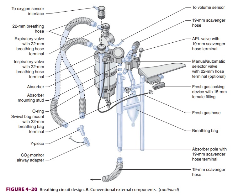
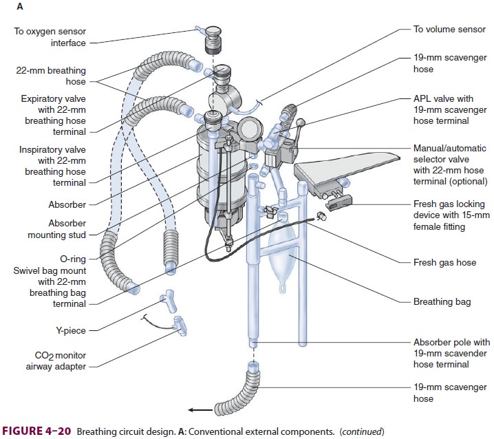
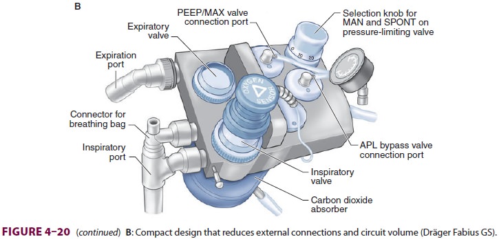
Newer anesthesia machines have
inte-grated internalized breathing circuit components (Figure 4–20). The advantages of
these designs include reduced probability of breathing circuit mis-connects,
disconnects, kinks, and leaks. The smaller volume of compact machines can also
help conserve gas flow and volatile anesthetics and allow faster changes in
breathing circuit gas concentration. Internal heating of manifolds can reduce
precipita-tion of moisture.
Oxygen Analyzers
General anesthesia should not be administered with-out an oxygen analyzer in the breathing circuit. Threetypes of oxygen analyzers are available: polaro-graphic (Clark electrode), galvanic (fuel cell), and paramagnetic. The first two techniques utilize elec-trochemical sensors that contain cathode and anode electrodes embedded in an electrolyte gel separated from the sample gas by an oxygen-permeable mem-brane (usually Teflon). As oxygen reacts with the electrodes, a current is generated that is proportional to the oxygen partial pressure in the sample gas. The galvanic and polarographic sensors differ in the com-position of their electrodes and electrolyte gels. The components of the galvanic cell are capable of pro-viding enough chemical energy so that the reaction does not require an external power source.
Although the initial cost of
paramagnetic sen-sors is greater than that of electrochemical sensors,
paramagnetic devices are self-calibrating and have no consumable parts. In
addition, their response time is fast enough to differentiate between inspired
and expired oxygen concentrations.
All oxygen analyzers should have a
low-level alarm that is automatically activated by turning on the anesthesia
machine. The sensor should be placed into the inspiratory or expiratory limb of
the circle system’s breathing circuit—but not
into the fresh gas line. As a result of the patient’s oxygen consumption, the
expiratory limb has a slightly lower oxygen par-tial pressure than the
inspiratory limb, particularly at low fresh gas flows. The increased humidity
of expired gas does not significantly affect most mod-ern sensors.
Spirometers
Spirometers, also called respirometers,
are used to measure exhaled tidal volume in the breathing cir-cuit on all
anesthesia machines, typically near the exhalation valve. Some anesthesia
machines also measure the inspiratory tidal volume just past the inspiratory
valve or the actual delivered and exhaled tidal volumes at the Y-connector that
attaches to the patient’s airway.
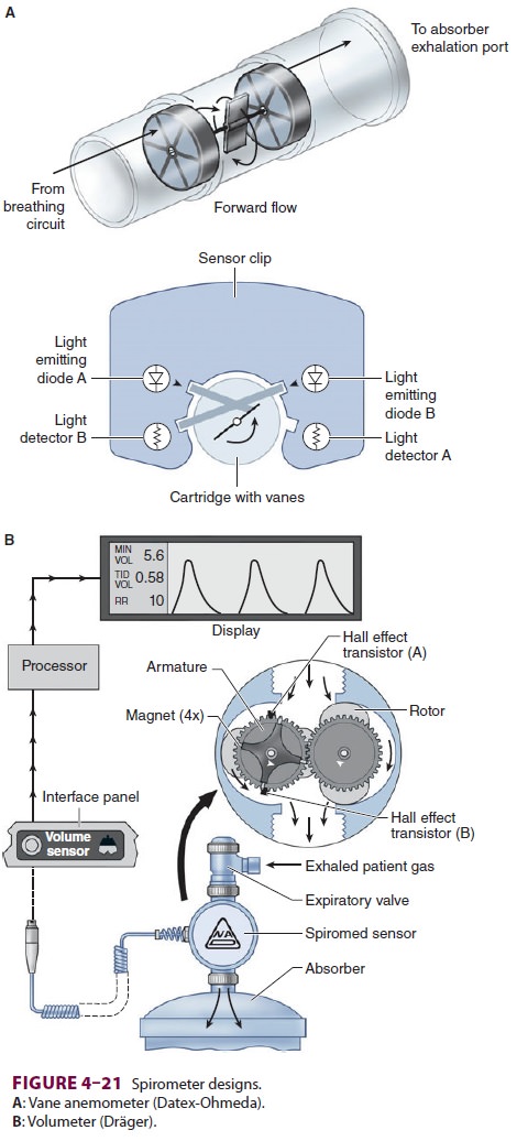
A common method employs a rotating vane
of low mass in the expiratory limb in front of the expi-ratory valve of the
circle system (vane anemometer or Wright respirometer, Figure 4–21A).The flow of gas
across vanes within the respi-rometer causes their rotation, which is measured
electronically, photoelectrically, or mechanically. In another variation using
this turbine principle, the volumeter or displacement meter is designed to
measure the movement of discrete quantities of gas over time (Figure 4–21B).
Changes in exhaled tidal volumes usually
rep-resent changes in ventilator settings, but can also be due to circuit
leaks, disconnections, or ventilator malfunction. These spirometers are prone
to errors caused by inertia, friction, and water condensa-tion. For example,
Wright respirometers under-read at low flow rates and over-read at high flow
rates. Furthermore, the measurement of exhaled tidal volumes at this location
in the expiratory limb includes gas that had been lost to the circuit (and not
delivered to the patient; discussed below). The difference between the volume
of gas delivered to the circuit and the volume of gas actually reach-ing the
patient becomes very significant with longcompliant breathing tubes, rapid
respiratory rates, and high airway pressures. These problems are at least
partially overcome by measuring the tidal vol-ume at the Y-connector to the
patient’s airway.A hot-wire anemometer utilizes a fine platinum wire,
electrically heated at a constant temperature, inside the gas flow. The cooling
effect of increasing gas flow on the wire electrode causes a change in
electrical resistance. In a constant-resistance ane-mometer, gas flow is
determined from the current needed to maintain a constant wire temperature (and
resistance). Disadvantages include an inability to detect reverse flow, less
accuracy at higher flow rates, and the possibility that the heated wire may be
a potential ignition source for fire in the breathing manifold.
Ultrasonic flow sensors rely on
discontinui-ties in gas flow generated by turbulent eddies in the flow stream.
Upstream and downstream ultra-sonic beams, generated from piezoelectric
crystals, are transmitted at an angle to the gas stream. The Doppler frequency
shift in the beams is proportional to the flow velocities in the breathing
circuit. Major advantages include the absence of moving parts and greater
accuracy due to the device’s independence from gas density.
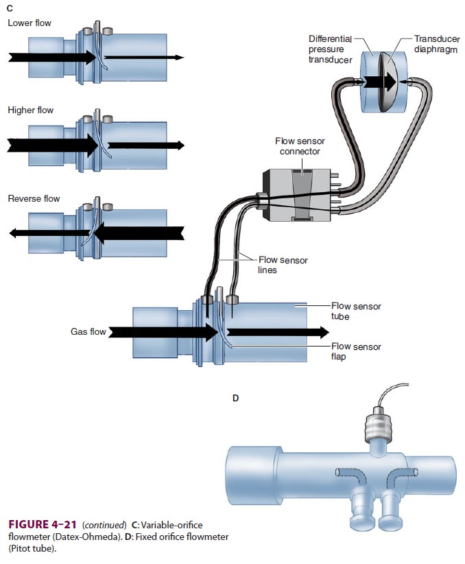
Machines with variable-orifice
flowmeters usu-ally employ two sensors ( Figure 4–21C). One mea-sures flow at the
inspiratory port of the breathing system and the other measures flow at the
expiratory port. These sensors use a change in internal diam-eter to generate a
pressure drop that is proportional to the flow through the sensor. Clear tubes
con-nect the sensors to differential pressure transduc-ers inside the
anesthesia machine (Datex-Ohmeda 7900 SmartVent). The changes in gas flows
during the inspiratory and expiratory phases help the ven-tilator to adjust and
provide a constant tidal volume. However, due to excessive condensation sensors
can fail when used with heated humidified circuits.
A pneumotachograph
is a fixed-orifice flow-meter that can function as a spirometer.
A parallelbundle of small-diameter tubes
in chamber (Fleisch pneumotachograph) or mesh screen provides a slight resistance
to airflow. The pressure drop across this resistance is sensed by a
differential pressure trans-ducer and is proportional to the flow rate.
Integration of flow rate over time yields tidal volume. Moreover, analysis of
pressure, volume, and time relationships can yield potentially valuable
information about air-way and lung mechanics. Modifications have been required
to overcome inaccuracies due to water con-densation and temperature changes.
One modifica-tion employs two pressure-sensing lines in a Pitot tube at the
Y-connection ( Figure
4–21D). Gas flow-ing through the Pitot tube (flow sensor tube)
creates a pressure difference between the flow sensor lines. This pressure
differential is used to measure flow, flow direction, and airway pressure. Respiratory
gases are continuously sampled to correct the flow reading for changes in
density and viscosity.
Circuit Pressure
A pressure gauge or electronic sensor is
always used to measure breathing-circuit pressure somewhere between the
expiratory and inspiratory unidirec-tional valves; the exact location depends
on the model of anesthesia machine. Breathing-circuit pressure usually reflects
airway pressure if it is measured as close to the patient’s airway as possible.
The most accurate measurements of both inspira-tory and expiratory pressures
can be obtained from the Y-connection (eg, D-lite and Pedi-lite sensors).
A rise in airway pressure may signal
worsen-ing pulmonary compliance, an increase intidal volume, or an obstruction
in the breathing cir-cuit, tracheal tube, or the patient’s airway. A drop in
pressure may indicate an improvement in compli-ance, a decrease in tidal
volume, or a leak in the cir-cuit. If circuit pressure is being measured at the
CO2 absorber, however, it will not always
mirror the pressure in the patient’s airway. For example, clamp-ing the
expiratory limb of the breathing tubes dur-ing exhalation will prevent the
patient’s breath from exiting the lungs. Despite this buildup in airway
pressure, a pressure gauge at the absorber will read zero because of the
intervening one-way valve.
Some machines have incorporated auditory
feedback for pressure changes during ventilator use.
Adjustable Pressure-Limiting Valve
The adjustable pressure-limiting (APL) valve, some-times referred to as the pressure relief or pop-off valve, is usually fully open during spontaneous ventilation but must be partially closed during manual or assisted bag ventilation. The APL valve often requires fine adjustments. If it is not closed suf-ficiently excessive loss of circuit volume due to leaks prevents manual ventilation. At the same time if it is closed too much or is fully closed a progressive rise in pressure could result in pulmonary barotrauma (eg, pneumothorax) or hemodynamic compromise, or both. As an added safety feature, the APL valves on modern machines act as true pressure-limiting devices that can never be completely closed; the upper limit is usually 70–80 cm H2O.
Humidifiers
Absolute humidity is defined as the
weight of water vapor in 1 L of gas (ie, mg/L). Relative humid-ity is the ratio
of the actual mass of water present in a volume of gas to the maximum amount of
water possible at a particular temperature. At 37°C and 100% relative humidity,
absolute humidity is 44 mg/L, whereas at room temperature (21°C and 100%
humidity) it is 18 mg/L. Inhaled gases in the operating room are normally
administered at room temperature with little or no humidification. Gases must
therefore be warmed to body temperature and saturated with water by the upper
respiratory tract. Tracheal intubation and high fresh gas flows bypass this
normal humidification system and expose the lower airways to dry (<10 mg H2O/L), room tem-perature gases.
Prolonged humidification of gases by the
lower respiratory tract leads to dehydration of mucosa, altered ciliary
function, and, if excessively pro-longed, could potentially lead to
inspissation of secretions, atelectasis, and even ventilation/per-fusion
mismatching, particularly in patients with underlying lung disease. Body heat
is also lost as gases are warmed and even more importantly as water is
vaporized to humidify the dry gases. The heat of vaporization for water is 560
cal/g of water vaporized. Fortunately, this heat loss accounts for about only
5–10% of total intraoperative heat loss, is not significant for a short
procedure (<1 h), and usually can easily be compensated for with a
forced-air warming blanket. Humidification and heating of inspiratory gases may
be most important for small pediatric patients and older patients with severe
underlying lung pathology, eg, cystic fibrosis.
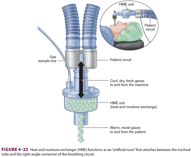
A. Passive Humidifiers
Humidifiers added to the breathing
circuit mini-mize water and heat loss. The simplest designs are condenser
humidifiers or heat and moisture exchanger (HME) units (Figure 4–22). These pas-sive
devices do not add heat or vapor but rather contain a hygroscopic material that
traps exhaled humidification and heat, which is released upon subsequent
inhalation. Depending on the design, they may substantially increase apparatus
dead space (more than 60 mL3), which can cause sig-nificant
rebreathing in pediatric patients. They can also increase breathing-circuit
resistance and the work of breathing during spontaneous respira-tions.
Excessive saturation of an HME with water or secretions can obstruct the
breathing circuit. Some condenser humidifiers also act as effective filters
that may protect the breathing circuit and anesthesia machine from bacterial or
viral cross-contamination. This may be particularly important when ventilating
patients with respiratory infec-tions or compromised immune systems.
B. Active Humidifiers
Active humidifiers are more effective
than passive ones in preserving moisture and heat. Active humid-ifiers add
water to gas by passing the gas over a water chamber (passover humidifier) or
through a satu-rated wick (wick humidifier), bubbling it through water
(bubble-through humidifier), or mixing it with vaporized water (vapor-phase
humidifier). Because increasing temperature increases the capacity of a gas to
hold water vapor, heated humidifiers with ther-mostatically controlled elements
are most effective.
The hazards of heated humidifiers include ther-mal lung injury (inhaled gas temperature should be monitored and should not exceed 41°C), noso-comial infection, increased airway resistance from excess water condensation in the breathing cir-cuit, interference with flowmeter function, and an increased likelihood of circuit disconnection. These humidifiers are particularly valuable with children as they help prevent both hypothermia and the plug-ging of small tracheal tubes by dried secretions. Of course, any design that increases airway dead space should be avoided in pediatric patients. Unlike pas-sive humidifiers, active humidifiers do not filter respiratory gases.
Related Topics