Chapter: Civil : Water Resources and Irrigation Engineering : Canal Irrigation
Need and Types Of Cross-Drainage Structure
NEED OF CROSS-DRAINAGE STRUCTURES
Aligning a canal on the watershed of an area is necessary so that water from the canal can by gravity to fields on both sides of the canal. However, a canal taking off from a river at has to necessarily cross some streams or drainages (such as a,b,c, and d in the before it can mount the watershed of the area at B. In order to carry canal is on the waters B, usually no cross-drainage structure is required except in situations when the canal leave a looping watershed (such as DEF in figure 11.1) for a short distance between D and may cross tributaries (as ate and f). Cross-drainage structures are constructed to negotiate aligned channel over, below, or at the same level of a stream .

TYPES OF CROSS-DRAINAGE STRUCTURE
The
cross-drainage structures can be classified under three broad categories
depending whether the structures is built to negotiate a carrier channel over,
below, or at the same level the stream channel.
Structures for a Carrier Channel Over a Natural Stream
Structures falling under this category are aqueducts and siphon aqueducts. Maintenance structures is relatively easy as these are above ground and can be easily inspected. The full supply level (FSL) of a canal is much higher than the high flood level (HFL) of a which, in turn, is lower than the bottom of the canal trough, the canal is carried over tream by means of a bridge-like structure, which is called an aqueduct. The stream water is through the space below the canal such that the HFL is lower than the underside of the trough, figure. 11.2
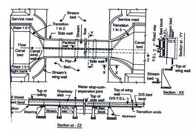
Figure: Typical plan and section of
an aqueduct (1)
Siphon Aqueduct (Figure) is an aqueduct in which
the bed of the stream is depressed passes under the canal trough, and the
stream water flows under pressure below the such aqueducts, the stream bed is
usually provided with a concrete or masonry floor.
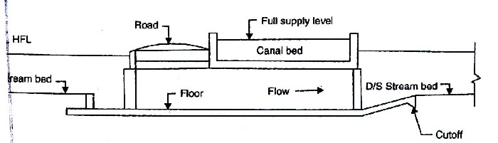
Figure: Siphon aqueduct
Aqueducts and siphon aqueducts are further classified into
the following types:
Type I: In this type of structure, the earthen
canal banks are carried as such and, the culvert length (i.e., the length of
barrels through which the stream water is passed u the canal) has to be long
enough to support the water section as well as the earthen ban the canal Figure
(a). In this type of structure, the canal section is not flumed and ram
unaltered. Hence, the width (across the canal) of the structure is maximum. This
type structure, obviously, saves on canal wings and banks connections and is
justified only for streams so that the length (along the canal) of the
structure is small. An extreme example such a structure would be when the
stream is carried by means of a pipe laid under the be the canal.
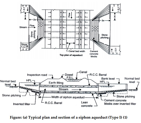
Figure: (a) Typical plan and section
of a siphon aqueduct (Type I) (1)
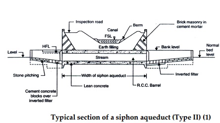
Type II:
This type of structure is similar to the Type I with provision of retaining was
to retain the outer slopes of the earthen canal banks figure (b). This reduces
the length the culvert. This type of construction can be considered suitable
for streams of intermedia size.
Type III: In this type of structure, the earthen
canal banks are discontinued through aqueduct and the canal water is carried in
a trough may be of either masonry or concre figure©. The earthen canal banks
are connected to the respective trough walls on the sides by means of wing
walls. The width of the canal is also reduced over the crossing. In the type of
structure, the width of the structure is minimum and, hence, the structure is
suitable for large streams requiring considerable length of aqueduct between
the abutments.
igure:
(b) Typical section of a siphon aqueduct (Type II) (1)
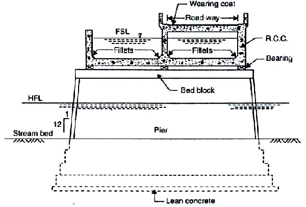
Figure: (c) Typical section of an
aqueduct (Type III) (1)
Structures for a Carrier channel Underneath a Natural
Stream
The
structures falling under this category are super passages and siphons. The
maintenance of such structures is relatively difficult as these are not easily
accessible.
A super passage Figure is like an aqueduct, but
carries the stream over the canal. The canal FSL is lower than the underside of
the stream trough and, hence, the canal water flows with a free surface.
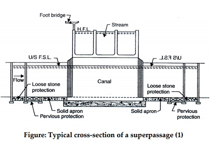
Figure: Typical cross-section of a
superpassage (1)
A siphon Figure carries the canal water under
pressure through barrels below the stream trough. For siphoning small
discharges, precast RCC pipes will be economical. For siphoning higher
discharges, horse-shoe-shaped rectangular or circular barrels, either single or
multiple, are adopted. Roofs or rectangular barrels are, at times, arch-shaped
for economy For discharges under high pressures, circular of horse-shoe-shaped
barrels are more suitable
Figure: Profile of a typical canal
siphon (1)
Structures for Carrier Channel Crossing a Natural Stream
at the Same Level
Structures
falling under this category are level crossings and inlets. Inlets are, at
times, combined with escapes. When the canal and the stream meet each other at
practically the level, a level crossing figure is provided. Level crossings
involve intermixing of the canal and stream waters. They are usually provided
when a large-sized canal crosses a large tream which carries a large discharge
during high floods, and when siphoning of either of the two is prohibitive on
considerations of economy and non-permissibility of head loss through siphon
barrels (1). A Barrier with its top at the canal FSL is constructed across the
stream and it the upstream end of the junction. The regulators are provided
across the stream and canal it the downstream junctions of the level crossing.
These regulators control the flow into the canal and stream downstream of the
crossing. This type of arrangement is also useful in augmenting the canal
supplies with the stream discharge.
Figure: Typical layout plan of a
level crossing (1)
When the
stream is dry, the stream regulator is kept closed and the canal regulator is
opened so that the canal water flows in the canal itself without interruption.
When the stream is bringing water, it mixes with the canal water and the stream
regulator is used the dispose of that part of the stream water which is not
used to augment the canal supply.
If a
small and relatively sediment-free stream meets the canal at practically the
same level (or its bed level is higher than the canal FSL ) then an inlet is
provided. An inlet is a structures consisting of an opening in a canal bank,
suitably protected, to admit upland stream water into the canal. Inlets are
constructed only if the stream discharge is too small and does not carry large
quantity of sediment. Inlets do not have a regulator and, hence, the stream
should be higher than the canal FSL. An inlet consists of a fall or a pitched
slope conf within wing walls to guide the stream water into the canal. An inlet
simply allows the stream water to be taken into the canal. If the stream water
so taken into the canal is appreciable quantity, it is allowed to flow out at a
suitable site downstream (along the canal) of the outlet is generally combined
with some other structures for economic reasons, but at only an inlet (and no
outlet) is provided.
Sometimes
a small stream is diverted into a larger stream and a cross-drainage struck for
the combined discharge is provided at a suitable site.
Related Topics