Chapter: Civil : Water Resources and Irrigation Engineering : Canal Irrigation
Alignment Of Irrigation Canals
ALIGNMENT OF IRRIGATION CANALS
Desirable
locations for irrigation canals on any gravity project, their cross-sectional
designs and construction costs are governed mainly by topographic and geologic
conditions along different routes of the cultivable lands. Main canals must
convey water to the higher elevations the cultivable area. Branch canals and
distributaries convey water to different parts of the indigable areas.
On projects where land slopes are relatively flat and uniform, it is advantageous align channels on the watershed of the areas to be irrigated. The natural limits of command such irrigation channels would be the drainages on either sides of the channel. Aligning a capacity (main branch as well as distributary) on the watershed ensures gravity irrigation on be can cross a canal aligned on the watershed. Thus, a canal aligned on the water shed saves cost of construction of cross-drainage structures. However, the main canal has to be taken from watershed in as host a distance as possible. Ground slope in the head reaches of a canal must mounting much higher than the required canal bed slope and, hence, the canal needs only a short distance to mount the watershed in as short a distance as possible. Ground slope in the head reaches of a canal much higher than the required canal bed slope and, hence, the canal needs only a short distance to mount the watershed. This can be illustrated by figure in which the main canal takes from a river at P and mounts the watershed at Q. Let the can bed level at P be m and elevation of the highest point N along the section MNP be 410 m. Assuming that the grow slopes is 1 m per km, the distance of the point Q (395 m) on the watershed from N would be km. If the required canal bed slope is 25 cm per km, the length PQ of the canal would be 20. Between P and Q, the canal would cross small streams and, hence, construction of cross-drainage structures would be necessary for this length. In fact, the alignment PQ is influence is considerably by the need of providing suitable locations for the cross-drainage structures would be necessary for this length. In fact, the alignment PQ is influence considerably by the need of providing suitable locations for the cross-drainage structures. In exact location of Q would be determined by trial so that the alignment PQ results in an economy as well as efficient system. Further, on the watershed side of the canal PQ, the ground higher than the ground on the valley side (i.e., the river side). Therefore, this part of the can irrigate only on one side (i.e., the river side) of the canal.
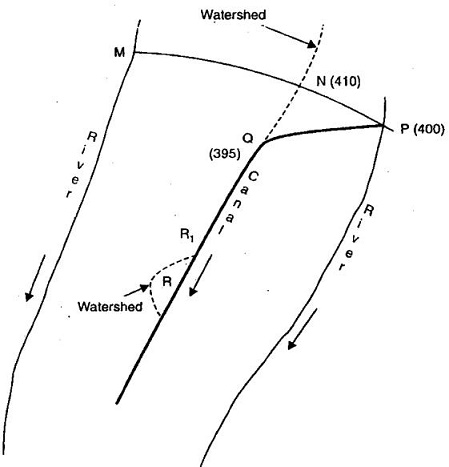
Figure: Head reach of a main canal in
plains
Once a
canal has reached the water shed, it is generally kept on the water shed,
except in chain situations, such as the looping watershed at R in figure. in an
effort to keep the canal alignment straight, the canal may have to leave the
water shed near R. the area between the canal and the watershed in the region R
can be irrigated by a distributary which takes off at R1 allows the water shed.
Also, in the region R, the canal may cross some small streams and, some
cross-drainage structures may have to be constructed. If watershed is passing
tough villages or towns, the canal may have to leave the watershed for some
distance.
In hilly areas, the conditions are vastly
different compared to those of plains. Rivers in valleys well below the
watershed or ridge, and it may not be economically feasible to the channel on
the watershed. In such situations, contour channels are constructed. Contour
channels follow a contour while the maintaining the required longitudinal. It
continues like this and as river slopes are much steeper than the required
canal bed the canal encompasses more area between itself and the river. It
should be that the more fertile areas in the hills are located at lower levels
only.
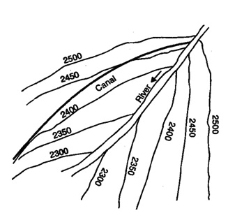
Figure: Alignment of main canal in
hills.
In order to finalise the channel network for a
canal irrigation project, trial alignments channels are marked on the map
prepared during the detailed survey. A large-scale map is carried to work out
the details of individual channels. However, a small-scale map depicting entire
command of the irrigation project is also desirable. The alignments marked on
the entire transferred on the field and adjusted wherever necessary. These
adjustments are referred on the map as well. The alignment on the field is
marked by small masonry pillars by 200 metres. The centre line on top of these
pillars coincides with the exact alignment between the adjacent pillars, a
small trench, excavated in the ground, marks the alignment.
Related Topics