Chapter: Television and Video Engineering : Colour Television Systems
NTSC Colour TV System
NTSC COLOUR TV SYSTEM
The NTSC colour system is compatible with the American 525 line monochrome system. In order to save bandwidth, advantage is taken of the fact that eye’s resolution of colours along the reddish blue-yellowish green axis on the colour circle is much less than those colours which lie around the yellowish red-greenish blue axis.
Therefore two new colour video signals, which correspond to these colour regions, are generated.
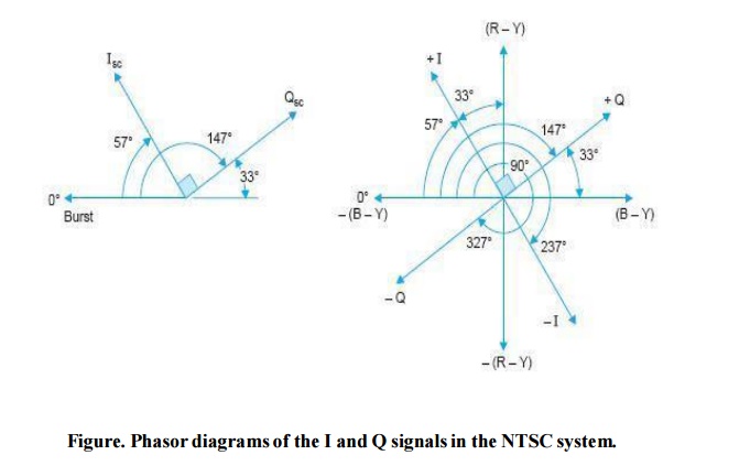
These are designated as I and Q signals.The I signal lies in a region 33° counter clockwise to + (R – Y) where the eye has maximum colour resolution. It* is derived from the (R – Y) and (B – Y) signals and is equal to 0.60R – 0.28G – 0.32B.
As shown in Fig. it is located at an angle of 57° with respect to the colour burst in the balanced modulator circuits. Similarly the Q** signal is derived from colour difference signals by suitable matrix and equals 0.21R –0.52G + 0.31B. It is located 33° counter clockwise to the +(B – Y) signal and is thus in quadrature with the I signal.
As illustrated in Fig. the Q signal covers the regions around magenta (reddish-blue) and yellow-green shades.
Similarly orange hues correspond to phase angles centred around + I and the
I = 0.74(R – Y) – 0.27(B – Y).
Q = 0.48(R – Y) + 0.41(B – Y).
complementary blue-green (cyan) hues are located around the diametrically opposite – I signal.Since the eye is capable of resolving fine details in these regions, I signal is allowed to possess frequencies up to 1.5 MHz.
However, the eye is least sensitive to colours that lie around the ± Q signals, and therefore it is allowed a bandwidth of only ± 0.5 MHz with respect to the colour subcarrier.
It may be noted that both I and Q signals are active up to 0.5 MHz and being at right angles to each other, combine to produce all the colours contained in the chrominance signal.
However, the Q signal drops out after 0.5 MHz and only I signal remains between 0.5 and 1.5 MHz to produce colours, the finer details of which the eyes can easily perceive.
To help understand this fact it may be recalled that only one colour difference signal is needed for producing colours which are a mixture of only two colours. Thus the Q signal is not necessary for producing colours lying in the region of orange (red + green) and cyan (green +blue) hues.
Hence at any instant when Q = 0 and only I signal is active the colours produced on the screen will run the gamut from reddish orange to bluish green.Bandwidth Reduction Double sideband transmission is allowed for the Q signal and it occupies a channel bandwidth of 1 MHz (± 0.5 MHz). However, for the I signal the upper sideband is restricted to a maximum of 0.5 MHz while the lower sideband is allowed to extent up to 1.5 MHz. As such it is a form of vestigial sideband transmission.
Thus in all, a bandwidth of 2 MHz is necessary for colour signal transmission. This is a saving of 1 MHz as compared to a bandpass requirement of 3 MHz if (B – Y) and (R – Y) are directly transmitted.It is now obvious that in the NTSC system, advantage is taken of the limitations of the human eye to restrict the colour signal bandwidth, which in turn results in reduced interference with the sound and picture signal sidebands.
The reduction in colour signal sidebands is also dictated by the relatively narrow channel bandwidth of 6 MHz in the American TV system.
Exact Colour Subcarrier Frequency The colour subcarrier frequency in the NTSC system has been chosen to have an exact value equal to 3.579545 MHz. The reason for fixing it with such a precision is to maintain compatibility between monochrome and colour systems.
Any interference between the chrominance signal and higher video frequencies is minimized by employing suppressed carrier (colour subcarrier) transmission and by using a notch filter in the path of the luminance signal. However, when a colour transmission is received on a monochrome receiver a dot pattern structure appears along each raster line on the receiver screen.
This is caused by the colour signal frequencies that lie within the pass-band of the video section of the receiver. As illustrated below such an interference can be eliminated if the subcarrier frequency is maintained at the exact value mentioned above. Assume that the interfering colour signal has a sinusoidal variation which rides on the average brightness level of the monochrome signal.
This produces white and black dots on the screen. If the colour subcarrier happens to be a multiple of the line frequency (n × f h ) the phase position of the disturbing colour frequency will be same on successive even or odd fields. Thus black and white dots will be produced at the same spots on the screen and will be seen as a persistent dot pattern interference.
However, if a half-line offset is provided by fixing the sub- carrier frequency to be an odd multiple of the half-line frequency, the disturbing colour signal frequency will have opposite polarity on successive odd and even fields. Thus as the same spot on the display screen a bright dot image will follow a dark one alternately.
The cumulative effect of this on the eye would get averaged out and the dot pattern will be suppressed. As an illustration of this phenomenon assume that a simple five line scanning system is being used. Figure shows the effect of sinewave luminance signal that is an odd harmonic of one-half of the scanning frequency.
Each negative excursion of the signal at the cathode of the picture tube will produce a unit area of brightness on the screen while the positive going excursions of the signal will cause unit dark areas on the picture.
In the illustration under consideration where the sinewave completes 3.5 cycles during one active horizontal line, four dark areas and three areas of brightness will be produced during the first line scan. Because of the extra half-cycle the next horizontal scan begins with an area of brightness and the entire line contains only three dark areas. the same off-set occurs on each succeeding line, producing a checkerboard pattern on the screen.
Since the scanning rate in the example utilizes an odd number of horizontal scans for each complete presentation, the luminance signal will be 180° out of phase with the previous signal as line number one is again scanned. Thus the pattern obtained on the screen will be the reverse of that which was generated originally.
The total effect of the above process on the human eye is one of cancellation. Since in
actual practice scanning takes place at a very fast rate, the presistency of the eye blends the patterns together with the effect that visibility of the dot structure is considerably reduced and goes unnoticed on a monochrome receiver.
The compatibility considerations thus dictate that the colour sub-carrier frequency (f sc ) should be maintained at 3.583125, i.e., (2 × 227 + 1) × 15750/2 MHz.
However, the problem does not end here, because the sound carrier and the colour sub-carrier beat with each other in the detector and an objectionable beat note of 0.92 MHz is produced (4.5 – 3.58 = 0.92).
This interferes with the reproduced picture. In order to cancel its cumulative effect it is necessary that the sound carrier frequency must be an exact multiple of an even harmonic of the line frequency.
The location of the sound carrier at 4.5 MHz away from the picture carrier cannot be disturbed for compatibility reasons and so 4.5 MHz is made to be the 286th harmonic of the horizontal deflection frequency. Therefore, f h = 4.5 MHz / 286 = 15734.26 Hz is chosen.
Note that this is closest to the value of 15750 Hz used for horizontal scanning for monochrome transmission.
A change in the line frequency necessitates a in the field frequency since 262.5 lines must be scanned per field. Therefore the field frequency (f v ) is changed to be 15734.26/262.5 = 59.94 Hz in place of 60 Hz.
The slight difference of 15.74 Hz in the line frequency (15750 – 15734.26 = 15.74 Hz) and of 0.06 Hz in the field frequency (60 – 59.94 = 0.06 Hz) has practically no effect on the deflection oscillators because an oscillator that can be triggered by 60 Hz pulses can also be synchronized to produce 59.94 Hz output.
Similarly the AFC circuit can easily adjust the line frequency to a slightly different value while receiving colour transmission.
As explained earlier the colour sub-carrier frequency must be an odd multiple of half the line frequency to suppress dot pattern interference. Therefore f sc is fixed at (2n + 1) f h /2, i.e., 455 × 15734.26/2 = 3.579545 MHz.
To obtain this exact colour sub-carrier frequency, a crystal controlled oscillator is provided. Encoding of Colour Picture Information Figure illustrates the enconding process of colour signals at the NTSC transmitter.
A suitable matrix is used to get both I and Q signals directly from the three camera outputs. Since I = 0.60R – 0.28G – 0.32B, the green and blue camera outputs are inverted before feeding them to the appropriate matrix. Similarly for Q = 0.21R – 0.52G + 0.31B, in invertor is placed at the output of green camera before mixing it with the other two camera outputs. anced modulators.
The subcarrier to the I modulator is phase shifted 57° clockwise with respect to the colour burst. The carrier is shifted by another 90° before applying it to the Q modulator. Thus relative phase shift of 90° between the two subcarriers is maintained for quadrature amplitude modulation.
It is the characteristic of a balanced modulator that while it suppresses the carrier and provides frequency translation, both the amplitude and phase of its output are directly related to the instantaneous amplitude and phase of the modulating signal.
Thus, with the subcarrier phase angles shifted to the locations of I and Q, the outputs from both the modulators retain full identity of the modulating colour difference signals. The sideband restricted output fromthe I modulator combines with the output of Q modulator to form the chrominance signal. It is then combined with the composite Y signal and colour burst in an adder to form composite chrominance signal. The output from the adder feeds into the main transmitter and modulates the channel picture carrier frequency. Note that colour subcarrier has the same frequency (3.579545 MHz) for all the stations whereas the assigned picture carrier frequency is different for each channel. A simplified block diagram of the NTSC colour receiver is shown in Fig.. The signal from the selected channel is processed in the usual way by the tuner, IF and video detector stages. The sound signal is separately detected, demodulated and amplified before feeding it to the loudspeaker. Similarly AGC, sync separator and deflection circuits have the same form as in monochrome receivers except for the inclusion of purity, convergence and pincushion correction circuits. At the output of video detector the composite video and chrominance signals reappear in their original premodulated form. The Y signal is processed as in a monochrome receiver except that the video amplifier needs a delay line. The delay line introduces a delay of about 500 ns which is necessary to ensure time coincidence of the luminance and chroma signals because of the restricted bandwidth of the latter.
Decoding of the Chroma (C) Signal
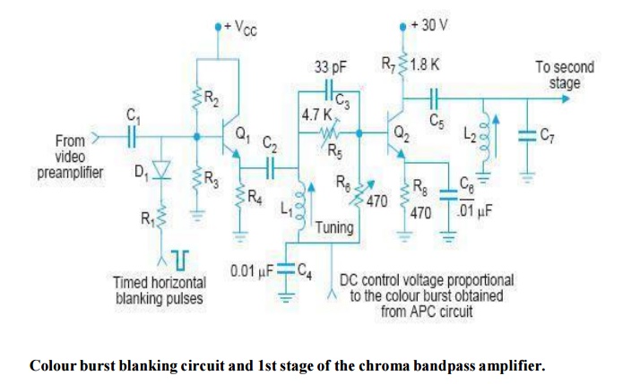
The block diagram of Fig. shows more details of the colour section of the receiver. The chroma signal is available along with other components of the composite signal at the output of the video preamplifier.
It should be noted that the chrominance signal has colour information during active trace time of the picture and the burst occurs during blanking time when there is no picture. Thus, although the ‘C’ signal and burst are both at 3.58 MHz, they are not present at the same time.
Chrominance Bandpass Amplifier
The purpose of the bandpass amplifier is to separate the chrominance signal from the composite video signal, amplify it and then pass it on to the synchronous demodulators.
The amplifier has fixed tuning with a bandpass wide enough ( ≈ 2 MHz) to pass the chroma signal. The colour burst is prevented from appearing at its output by horizontal blanking pulses which disable the bandpass amplifier during the horizontal blanking intervals. The blanking pulses are generall y applied to the colour killer circuit which is turn biases-off the chrominance amplifier during these periods.
Colour Demodulators
Synchronous demodulators are used to detect the molulating signal. Such a demodulator may be thought of as a combination of phase and amplitude detectors because the output is dependent on both phase and amplitude of the chroma signal. As shown in the block diagram (Fig) each demodulator has two input signals, the chroma which is to be demodulated and a constant amplitude output from the local subcarrier oscillator. ∠The oscillator output is coupled to the demodulators by phase-shifting networks. The I
demodulator oscillator voltage has a phase of 57° with respect to the burst phase (f sc 0°) and so has the correct delay to detect the I colour difference signal. Similarly the oscillator voltage to the Q demodulator is delayed by 147° (57° + 90°) for detecting the Q colour-difference signal. Thus the I and Q synchronous demodulators convert the chroma signal (a vector quantity) into its right-angle components (polar to rectangular conversion).
The Colour Matrix
This matrix is designed to produce (R – Y), (G – Y) and (B – Y) signals from the I and Q video signals. Colour difference signal amplifiers are required to perform two functions. While amplifying the signals they also compensate for the chroma signal compression (weighting factors) that was introduced at the transmitter as a means of preventing overmodulation.
The (R – Y) amplifier provides a relative boost of 1.14 = 1/87.7% while the (B – Y) amplifier does so by a factor of 2.03 = 1/49%. Similarly the (G – Y) amplifier reduces its output level to become 0.7(70%) in a relative sense.
The grids and cathode of the picture tube constitute another matrix. The grids are fed positive colour difference signals and the cathode receives – Y signal.
The resultant voltages between the three grids and cathode become:
(R – Y) – (– Y) = R, (G – Y) – (– Y) = G and (B – Y) – (– Y) = B
and so correspond to the original red, green and blue signals generated by the colour camera at the transmitting end.
Burst Separator
The burst separator circuit has the function of extracting 8 to 11 cycles of reference colour burst which are transmitted on the back porch of every horizontal sync pulse.
The circuit is tuned to the subcarrier frequency and is keyed ‘on’ during the flyback time by pulses derived from the horizontal output stage.
The burst output is fed to the colour phase discriminator circuit also known as automatic frequency and phase control (AFPC) circuit.
Colour Subcarrier Oscillator
Its function is to generate a carrier wave output at 3.579545 MHz and feed it to the demodulators. The subcarrier frequency is maintained at its correct value and phase by the AFPC circuit.
Thus, in a way the AFPC circuit holds the hue of reproduced colours at their correct values.
Colour Killer Circuit
As the name suggests this circuit becomes ‘on’ and disables the chroma bandpass amplifierduring monochrome reception.
Thus it prevents any spurious signals which happen to fall within the bandpass of the chroma amplifier from getting through the demodulators and causing coloured interference on the screen.
This colour noise is called ‘confetti’ and looks like snow but with large spots in colour. The receiver thus automatically recognizes a colour or monochrome signal by the presence or absence of the colour sync burst.
This voltage is processed in the AFPC circuit to provide a dc bias that cuts off the colour killer circuit. Thus when the colour killer circuit is off the chroma bandpass amplifier is ‘on’ for colour information.
In some receiver designs the colour demodulators are disabled instead of the chroma bandpass amplifier during monochrome reception.
Manual Colour Controls
The two additional operating controls necessary in the NTSC colour receivers are colour (saturation) level control and tint (hue) control.
These are provided on the front panel of the colour receiver. The colour control changes the gain of the chrominance bandpass amplifier and thus controls the intensity or amount of colour in the picture.
The tint control varies phase of the 3.58 MHz oscillator with respect to the colour sync burst. This circuit can be either in the oscillator control or AFPC circuit.
LIMITATIONS OF THE NTSC SYSTEM
The NTSC system is sensitive to transmission path differences which introduce phase errors that results in colour changes in the picture.
At the transmitter, phase changes in the chroma signal take place when changeover between programmes of local and television network systems takes place and when video tape recorders are switched on.
The chroma phase angle is also effected by the level of the signal while passing through various circuits. In addition crosstalk between demodulator outputs at the receiver causes colour distortion.
All this requires the use of an automatic tint control (ATC) circuit with provision of a manually operated tint control.
Related Topics