Chapter: Television and Video Engineering : Colour Television Systems
SECAM system
SECAM SYSTEM
The SECAM system was developed in France. The fundamental difference between the SECAM system on the one hand and the NTSC and PAL systems on the other is that the latter transmit and receive two chrominance signals simultaneously while the SECAM system is ‘‘sequential a memoire’’, i.e., only one of the two colour difference signals is transmitted at a time.
The subcarrier is frequency modulated by the colour difference signals before transmission. The magnitude of frequency deviation represents saturation of the colour and rate of deviation its fineness.
If the red difference signal is transmitted on one line then the blue difference signal is transmitted on the following line. This sequence is repeated for the remaining lines of the raster. Because of the odd number of lines per picture, if nth line carriers (R – Y) signal during one picture, it will carry (B – Y) signal during scanning of the following picture.
At the receiver an ultrasonic delay line of 64 μs is used as a one line memory device to produce decoded output of both the colour difference signals simultaneously.
The modulated signals are routed to their correct demodulators by an electronic switch operating at the rate of line frequency. The switch is driven by a bistable multivibrator triggered from the receiver’s horizontal deflection circuitry.
The determination of proper sequence of colour lines in each field is accomplished identification (Ident) pulses which are generated and transmitted during vertical blanking intervals.
SECAM III
During the course of development the SECAM system has passed through several stages and the commonly used system is known as SECAM III. It is a 625 line 50 field system with a channel bandwidth of 8 MHz.
The sound carrier is + 5.5 MHz relative to the picture carrier. The nominal colour subcarrier frequency is 4.4375 MHz. As explained later, actually two subcarrier frequencies are used.
The Y signal is obtained from the camera outputs in the same way as in the NTSC and PAL systems.
However, different weighting factors are used and the weighted colour difference signals are termed D R and D B where |D R | = 1.9 (R – Y) and |D B | = 1.5 (B – Y).
Modulation of the Subcarrier
The use of FM for the subcarrier means that phase distortion in the transmission path will not change the hue of picture areas.
Limiters are used in the receiver to remove amplitude variations in the subcarrier. The location of subcarrier, 4.4375 MHz away from the picture carrier reduces interference and improves resolution.
In order to keep the most common large deviations away from the upper end of the video band, a positive frequency deviation of the subcarrier is allowed for a negative value of (R – Y).
Similarly for the blue difference signals a positive deviation of the subcarrier frequency indicates a positive (B – Y) value. Therefore, the weighted colour signals are: D R = – 1.9 (R – Y) and D B = 1.5 (B – Y).
The minus sign for D R indicates that negative values of (R – Y) are required to give rise to positive frequency deviations when the subcarrier is modulated.
In order to suppress the visibility of a dot pattern on monochrome reception, two different subcarriers are used. For the red difference signal it is 282 f H = 4.40625 MHz and for the blue difference signal it is 272 f H = 4.250 MHz.
Pre-emphasis
The colour difference signals are bandwidth limited to 1.5 MHz. As is usual with frequencymodulated signals the SECAM chrominance signals are pre-emphasised before they are transmitted.
On modulation the subcarrier is allowed a linear deviation = 280 D R KHz for the red difference signals and 230 D B KHz for the blue difference signals. The maximum deviation allowed is 500 KHz in one direction and 350 KHz in the other direction for each signal although the limits are in opposite directions for the two chrome signals.After modulating the carrier with the pre-emphasised and weighted colour difference signals (D R and D B ), another form of pre-emphasis is carried out on the signals.
This takes the form of increasing the amplitude of the subcarrier as its deviation increases. Such a pre-emphasis is called high-frequency pre-emphasis. It further improves signal to noise ratio and interference is very much reduced.
Line Identification Signal The switching of D R and D B signals line-by-line takes place during the line sync pulse period.
The sequence of switching continues without interruption from one field to the next and is maintained through the field blanking interval. However, it is necessary for the receiver to be able to deduce as to which line is being transmitted.
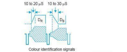
Such an identification of the proper of colour lines in each field in accomplished by identification pulses that are generated during vertical blanking periods. The signal consists of a sawtooth modulated subcarrier (see Fig.) which is positive going for a red colour-difference signal and negative going for the blue colour- difference signal.
At the receiver the Ident pulses generate positive and negative control signals for regulating the instant and sequence of switching.
SECAM Coder
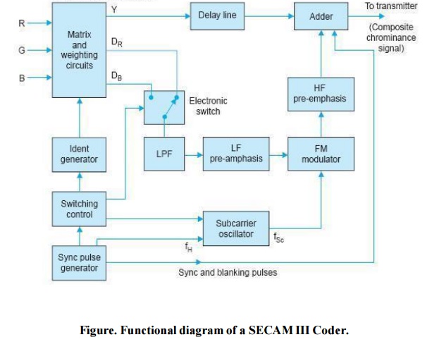
Figure is a simplified functional diagram of a SECAM III coder. The colour camera signals are fed into a matrix where they are combined to form the luminance (Y = 0.3R + 0.59G + 0.11B) and colour-difference signals.
The SECAM weighting and sign factors are applied to the colour-difference signals so that the same subcarrier modulator can be used for both the chrominance (D R and D B ) signals. The Ident signal is also added in the same matrix.
An electronic switch which changes its mode during every line blanking interval directs D R and D B signals to the frequency modulator in a sequential manner, i.e., when D R is being transmitted on the line, then D B is not used and vice versa. S ync Pulse Generation and Control The line frequency pulses from the sync pulse generator are passed through selective filters which pick out the 272nd and 282nd harmonics of f H .
These harmonics are amplified and used as the two subcarrier references. The sync pulse generator also synchronizes the switching control unit which in turn supplies operating pulses to the electronic switch for choosing between D R and D B signals.
The switching control also operates the circuit which produces modulated waveforms of the Ident signal. These are added to the chrominance signals during field blanking period and before they are processed for modulation.
The output from the electronic switch passes through a low-pass filter which limits the bandwidth to 1.5 MHz. The bandwidth limited signals are pre-emphasized and then used to frequency modulate the subcarrier.
The modulator output passes through a high frequency pre-emphasis filter having a bell-shaped response before being added to the Y signal.
The sync and blanking pulses are also fed to the same adder. The adder output yields composite chrominance signal which is passed on to the main transmitter.
SECAM Decoder
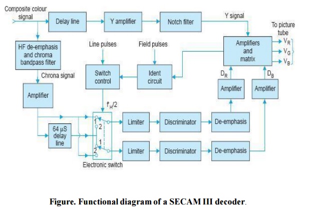
SECAM receivers are similar in most respects to the NTSC and PAL colour receivers and employ the same t ype of colour picture tubes. The functional diagram of a SECAM III decoder is shown in Fig..
The chroma signal is first filtered from the composite colour signal. The bandpass filter, besides rejecting unwanted low frequency luminance components, has inverse characteristics to that of the bell-shaped high frequency pre-emphasis filter used in the coder.
The output from the bandpass filter is amplified and fed to the electronic line-by-line switch via two parallel paths. The 64 μs delay lines ensures that each transmitted signal is used twice, one on the line on which it is transmitted and a second time on the succeeding line of that field.
The electronic switch ensures that D R signals, whether coming by the direct path or the delayed path, always go to the D R demodulator. Similarly D B signals are routed only to the D B demodulator. i.e., it is directing D R and D B signals to the wrong demodulators, the output of each demodulator during the Indent signal period becomes positive instead of negative going. A sensing circuit in the Ident module then changes the switching phase.
The electronic switch directs the frequency modulated signals to limiters and frequency discriminators. The discriminators have a wider bandwidth than that employed for detecting commercial FM sound broadcasts.
After demodulation the colour difference signals are de- emphasized with the same time constant as employed while pre-emphasing. As in other receivers the matrix networks combine the colour difference signals with the Y signal to give primary colour signals R, G and B which control the three electronic beams of the picture tube.
It may be noted that a SECAM receiver requires only two controls—brightness and constrast, both for monochrome and colour reception. The saturation and hue controls are not needed because the system is immune to these distortions.
This is so because the colour signals are constant amplitude, frequency modulated signals and the frequency deviations which carry colour information are not affected during transmission.
MERITS AND DEMERITS OF SECAM SYSTEMS
Several advantages accrue because of frequency modulation of the subcarrier and transmission of one line signal at a time. Because of FM, SECAM receivers are immune to phase distortion.
Since both the chrominance signals are not present at the same time, there is no possibility of cross-talk between the colour difference signals. There is no need for the use of Q.A.M. at the transmitter and synchronous detectors at the receiver.
The subcarrier enjoys all the advantages of FM. The receiver does not need ATC and ACC circuits. A separate manual saturation control and a hue control are not necessary. The contrast control also serves as the saturation control.
All this makes the SECAM receiver simple and cheaper as compared to NTSC and PAL receivers. It may be argued that the vertical resolution of the SECAM system is inferior since one line signal combines with that of the previous to produce colours.
However, subjective tests do not bring out this deficiency since our visual perception for colours is rather poor. In addition, while SECAM is a relatively easy signal to record there is one serious drawback in this system.
Here luminance is represented by the amplitude of a voltage but hue and saturation are represented by the deviation of the sub-carrier. When a composite signal involving luminance and chrominance is faded out in studio operation it is the luminance signal that is readily attenuated and not the chrominance.
This makes the colour more saturated during fade to black. Thus a pink colour will change to red during fade-out. This is not the case in NTSC or PAL systems. Mixing and lap dissolve presents similar problems.
In conclusion it may be said that all television systems are compromises since changing one parameter may improve one aspect of performance but degrade another, for example increasing bandwidth improves resolution of the picture but also increases noise.
In fact when all factors are taken into account it is difficult to justify the absolute superiority of one system over the other. In many cases political and economic factors have been the apparent considerations in adopting a particular monochrome and the compatible colour system.
It can therefore be safely concluded that the three colour systems will co-exist. Possibly some consensus on international exchange will be reached in due course of time.
Related Topics