Chapter: Television and Video Engineering : Colour Television Systems
PAL Colour Television System
PAL COLOUR TELEVISION SYSTEM
The PAL system which is a variant of the NTSC system, was developed at the Telefunken Laboratories in the Federal Republic of Germany. In this system, the phase error susceptibility of the NTSC system has been largely eliminated.
The main features of the PAL system are: (i) The weighted (B – Y) and (R – Y) signals are modulated without being given a phase shift of 33° as is done in the NTSC system. (ii) On modulation both the colour difference quadrature signals are allowed the same bandwidth of about 1.3 MHz.
This results in better colour reproduction. However, the chroma signal is of vestigial sideband type. The upper sideband attenuation slope starts at 0.57 MHz, i.e., (5 – 4.43 = 0.57 MHz) but the lower sideband extends to 1.3 MHz before attenuation begins. (iii)
The colour subcarrier frequency is chosen to be 4.43361875 MHz. It is an odd multiple of one-quarter of the line frequency instead of the half-line offset as used in the NTSC system. This results in somewhat better cancellation of the dot pattern interference.(iv)
The weighted (B – Y) and (R – Y) signals are modulated with the subcarrier in the same way as in the NTSC system (QAM) but with the difference, that phase of the subcarrier to one of the modulators (V modulator) is reversed from + 90° to – 90° at the line frequency. In fact the system derives its name, phase alteration by line (i.e., PAL), from this mode of modulation.
This technique of modulation cancels hue errors which result from unequal phase shifts in the transmitted signal.
As explained earlier the (B – Y) and (R – Y) subcarrier components in the chrominance signal are scaled down by multiplying them with the ‘weighting’ factors. For brevity the weighted signals are then referred to as U and V components of the chrominance signal where U = 0.493 (B – Y) and V = 0.877 (R – Y).
Thus as illustrated in Fig. C PAL = U sin ω s t ± V cos ω s t = U 2 + V 2 sin (ω s t ± θ) where tan θ = V/U The switching action naturally occurs during the line blanking interval to avoid any visible disturbance.

The PAL Burst
If the PAL signal were applied to an NTSC type decoder, the (B – Y) output would be U as required but the (R – Y) output would alternate as + V and – V from line to line. Therefore, the V demodulator must be switched at half the horizontal (line) frequency rate to give ‘+ V ’ only on all successive lines.
Clearly the PAL receiver must be told how to achieve the correct switching mode. A colour burst (10 cycles at 4.43 MHz) is sent out at the start of each line. Its function is to synchronize the receiver colour oscillator for reinsertion of the correct carrier into the U and V demodulators.
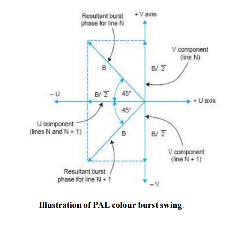
While in NTSC the burst has the phase of – (B – Y) and a peak-to-peak amplitude equal to that of the sync, in PAL the burst is made up to two components – (B – Y) component as in NTSC but with only 1/ 2 of the NTSC amplitude and an (R – Y) component which like all the (R – Y) information is reversed in phase from line to line.
This ± (R – Y) burst signal has an amplitude equal to that of the – (B – Y) burst signal, so that the resultant burst amplitude is the same as in NTSC.
Note that the burst phase actually swings m 45° see about the – (B – Y) axis from line to line. However the sign of (R – Y) burst component indicates the same sign as that of the (R – Y) picture signal.
Thus the necessary switching mode information is always available. Since the colour burst shifts on alternate lines by ± 45° about the zero reference phase it is often called the swinging burst.

Related Topics