Chapter: Fiber optics and Laser instruments : Industrial Application of Fiber Optical Sensor
Measurement using fiber optics sensor
Measurement using fiber optics
sensor:
1. Measurement of pressure:
All the
displacement sensors can be used to measure pressure. Here the pressure is
first converted in to displacement and the change in intensity is reflected or
transmitted light is measured in terms of displacement. The pressure sensor
based on reflective concept. Depending upon the value of pressure, the radius
of curvature of the diaphragm is changed. Hence, the intensity of the reflected
light is changed. The response curve shows that as the pressure increases,
output voltage decreases. With increase of pressure, the intensity of reflected
light is decreased and hence the output voltage decreases.
2. Measurement of temperature:
The
bimetallic strip acts as a sensing element. It consist of steel and brass which
are welded together to form a strip. The brass has higher linear expansively
compared to steel. The strip is attached to a bifurcated reflective fiber optic
probe. The strip is designed to move continuously and its movement is
directionally proportional to temperature. The amount of reflected light is
converted in to voltage by a photodiode.
The
amount of light reflected decreases with increase of temperature. So that output
of photodiode decreases with increase of temperature.
3. Phase modulated temperature
sensor:
Here ,
the phase shift produced in the sensing relative to reference fiber is a
function of temperature. This is given by the equation,
The
arrangement is called mach-zender.
The
Semiconductor laser acts as a light source.
A 3 db
splitter acts as the beam splitter which sense the light through the sensing
and reference fiber.
Another 3
dB coupler acts as a combiner of these two beams.
A series
of light and dark fringes are formed when light form two fiber interface on the
display screen.
A phase
changes of 2φ radians causes a displacement of 1 fringe.
By
counting the fringe displacement, The magnitude of temperature is determined.
If is
negligible. By placing a photodetector to measure the intensity of the fringes,
we can get sensitivity as
By taking
the difference between the two output signals from the sensing fiber and
reference fiber, Sensitivity of the sensor is doubled.
4. Measurement of current:
The
linearly polarized laser light from the negative laser is launched in to fiber.
Cladding mode stripper removes cladding modes. The direction of polarization of
the light in the fiber rotated by the longitudinal magnetic field around the
current carrying conductor.

The
returning light from the fiber loop is passed through the Wallaston prism which
is used to sense the resulting rotation and it resolves the emerging light in
to two orthogonal components I1 and I2 . these components
are separately detected by photodiode detectors and the difference and sum of
these signals are found out
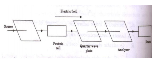
5. Measurement of voltage
The
variation of refractive index with respect to electric field E is written as
In this
crystal, when we apply electric field/ voltage along Z axis, the light which is
linearly polarized at an angle 45° with respect to X axis under goes a phase
shift or phase retardation.
If I0be
the incident light intensity , then the intensity of the transmitted light
through crystal is I=I0sin2 . Thus , phase produced in the linearly
polarized wave is directly proportional to![]() applied electric field/ voltage. The polarizer
converts the incident ordinary light in to a linearly polarized light. When
there is applied voltage across the pocket cell, phase shift is produced for
the transmitted polarized beam. Quarter wave plate produces a phase shift of θ/2.
The transmitted light is then analysed through a analyzers. The transmitted
light intensity can be written as,
applied electric field/ voltage. The polarizer
converts the incident ordinary light in to a linearly polarized light. When
there is applied voltage across the pocket cell, phase shift is produced for
the transmitted polarized beam. Quarter wave plate produces a phase shift of θ/2.
The transmitted light is then analysed through a analyzers. The transmitted
light intensity can be written as,
Measurement of strain:
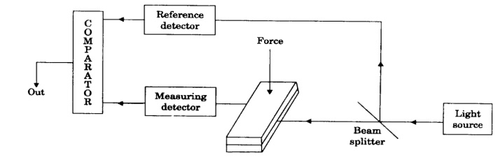
Micro
bending losses are produced in the fiber when the top block presses the fiber
by the applied external force. The micro bend losses are found to increase in
force applied to the top block. The intensity changes produced by the applied
force are measured with reference to a direct unmodulated signal from the light
source. The comparator compares these two values and gives the value of strain
produced.
6. Measurement of liquid level
Liquid
level sensor consists of two fibers which are connected at the base of a glass
micro prism. When the tip of the prism is immersed in the liquid, there is no
output at the detector. When the tip of the prism is just above the liquid
level, due to contact with air, there is total internal reflection and output
is got in the detector.
Disadvantage:
Not
useful for sensing multi liquid level since it operates in digital mode.
Related Topics