Chapter: Fiber optics and Laser instruments : Industrial Application of Fiber Optical Sensor
Fiber Optic Instrumentation System
Fiber Optic Instrumentation
System
1. 1ntroduction
The
communication engineers need the fiber characteristics to design the optical
fiber link with an efficient waveguide without any loss or dispersion.
Similarly, the fiber manufactures ned the fiber characteristics for further
development. Generally, the fiber attenuation measurement are used to determine
repeaters spacing and light source power dispersion measurements are used to
determine the maximum bit rate. Refractive index profile measurement are to
know the number of modes propagating the fiber and to determine its numerical
aperature.
2. Measurement of attenuation (by
cut back method)
Light
from a halogen lamp or white light source is couple into the experimental fiber
having length about 1 km. The lens placed in front of the source focuses the
light on to the interference filter or monochromatic prism or grating. The
light with a given wavelength is incident on the chopper which is used to
convert d.c light into square pulses of light (a.c). It also sends the
reference signal to the lock in amplifier. Monitor is used to view the
intensity of the optical beams. The cladding mode strippers are connected at
the input end and output end of fiber. The cladding mode stripper is used to
remove the cladding light or cladding modes. Then the jacket fiber is placed in
an index matching liquid whose refractive index is slightly higher than that of
cladding.
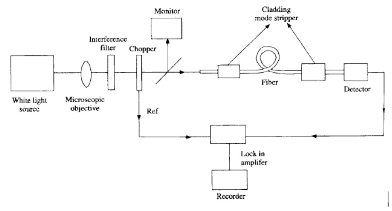
This
arrangement is called cladding mode stripper which will attenuate the light
propagating through the cladding. After travelling through the fiber of 1Km
length, the given height reaches the index matched photodetector whose output
is given to the lock amplifier. The lock amplifier delivers a output to the
recorder or nanovoltmeter. Then the fiber is cut back, leaving typically 2m of
the fiber and the experiment is repeated. In this case the output power is
noted Pr (λ) is noted. This procedure is repeated for other wavelength
also. Thus the fiber attenuation at a given wavelength ‘λ’ is given by,
Where L
is the length of the fiber cut back in Km. In the case of multimode fibers,
there are mode scrambler used to get the uniform intensity distribution among
all the modes and order sorting filter acting as a mode selector to determine
the fiber loss for each mode.
Advantage:
This
method is very accurate and simple.
Drawback
i)
This method cannot be utilized to find the fiber
attenuation in a working fiber optic link.
ii)
It is a destructive testing method.
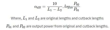
3.
Optical domain reflectometers:
The OTDR is the instrument which is used both in
laboratory and field measurements for determining fiber attenuation ,joint
losses and detecting fault losses. When the fiber attenuation varies with
distance, then the OTDR is the only instrument which can measure the fiber
attenuation along the fiber optics link. The OTDR measurement is a
non-destructive measurement.
Principle:
This method is often called the both scatter
method. It is based on the measurement and analysis of the fraction of light
which is reflected back within the numerical aperture of the fiber due to
Rayleigh scattering.
Construction and working:
A light pulse from a pulsed laser is launched into
the fiber through a directional coupler. The back scattered light from the
fiber is received by a photo detector like APD, through the directional
coupler. A box car integrator is mainly used to improve S/N ratio by taking
arithmetic average over a number of measurements taken at one point within the
fiber. The signal from the integrator is fed to the logarithmic amplifier and
its output is given to the recorder in DB. The recorder will display the
averaged measurements for successive points within the fiber .The intial

peak is
caused by the reflection at the fiber end. The reflection from the input
coupler is as small increase in the reflected power. There is a long tail
caused by Rayleigh scattering of the input pulse as it travels through the
fiber link in the forward direction. Due to presence of a fault in the fiber
link. There is a sudden decrease of reflected power. Next peak is caused by
splice or joint. Finally there is a peak due to Fresnel reflection of the fiber
end where the reflected power is more than that of splice.
4. Fiber
scattering loss Measurement:
Usually a high power laser source like He-Ne laser
or Nd-YAG laser is used to provide sufficint input optical power to the fiber.
The focusing lens focuses the light into the input end of the fiber having
short length. Before and after the scattering cell or integrating sphere, the
cladding mode strippers are used to avoid the light propagating in the cladding
so that the scattering measurement is taken only for the light guided by the
fiber core. Further the output end of the fiber is in index matched liquid to
avoid reflections contributing to the optical signal within the integrating
sphere. The light scattered from the fiber core is detected by the series solar
cell in the integrating sphere. The integrating sphere also contains the index
matching liquid surrounding the fiber. The detected signal by the series of
solar cell gives the measurement of the scattered signal. The detected signal
is given to lock in amplifier an to then to the recorder or nano voltmeter.
5. Fiber
Absorption Measurement:
Fiber
absorption measurement will give the impurity level in the filter.
Fiber
absorption loss(bB/km)= Fiber attenuation loss (dB/Km)- Fiber scattering
loss(dB/km)
Thus the fiber absorption lass istrhe difference
between fiber attenuation loss and scattering loss.
Principle: Amount of
light energy absorbed by the fiber= Heat energy developed in the calorimeter
Construction:Here
there are two fibers one is the fiber under measurement and other is the dummy fiber. The dummy fiber is meant
for compensation of any radiation loss of heat energy developed. These two
fibers are mounted separately in silica capillary tubes surrounded by the low
refractive index liquid like methanol in the calorimeter for good electrical
contact. The light from the laser source is well focused on the fiber under
measurement. The dummy fiber is not connected with light input. Then the fiber
guided light is inserted into the cladding mode stripper which removes the
light propagated in the cladding of the fiber. After passing through the
capillary tube, The fiber with light is immersed in the index matching liquid
to avoid reflections contributing to the optical signal within the capillary
tube.
Procedure;
When the
light enters the fiber under measurement there is a temperature rise in the
capillary tube containing the fiber with light. The temperature rise due to
absorption tube containing the fiber with light. The temperature rise due to
absorption of energy by the fiber is measured for every 10 seconds by a
thermocouple which is spirally around the silics tubes. The hot junction of the
thermocouple and the cold junction of the thermocouple are connected with a
nanovoltmeter. Electrical calibration is done by placing a thin wire instead of
fiber such that and passing known amount of current such that
mST=I2RT=VIt
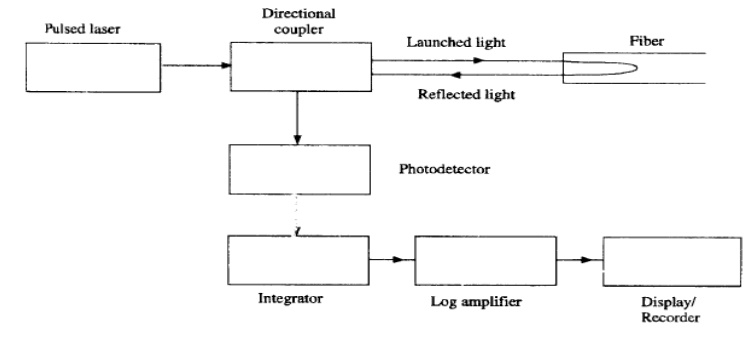
6. Fiber
dispersion measurements:
Dispersion is measured in terms of pulse
broadening. There are two types of fiber dispersions. One is intermodal
dispersion and the other is intra nodal (or) chromatic dispersion. Both dispersion
measurements can be performed using the the same exceptthe light source.
Internodal dispersion measurement is made by the monochromatic laser with
narrow spectral width. This intermodal dispersion is dominant in the multimode
fibers. The intra nodal dispersion measurement is made by the injection laser
whose frequency or line width increases with respect to time.
The laser
with driver circuit gives short narrow pulses of light. The laser light is
focused onto the beam splitter. The beam splitter is used for triggering the
oscilloscope and for input pulse with measurement. One of the beams passing
through the beam splitter is again focused into the fiber under measurement.
Normally its length is 1 km .The focused output laser beam is incident on the
avalanche photodiode and it gives the output pulses. The input pulse and output
pulse are displayed separately on the screen of sampling oscilloscope and they
are in Gaussian shape.
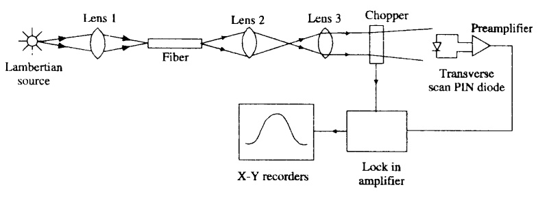
7. End
reflection method:
The light from the lambertian source is focused
onto the entrance end of the fiber having a length 2 metre. The magnified image
of the output end of the fiber is obtained by a lens arrangement and is then
passed through chopper. The near field of the output of the chopper is scanned
transversly by a p-i-n detector . The detector output is amplified by a
preamplifier. The chopper and the preamplifier are linked with the lock in
amplifier. So the phase sensitive detected signal is further amplified and
plotted directly on a X-Y recorder. For a graded index fiber, the display
appears in the form of a Gaussian curve and for a step index fiber it appears
in the form of a rectangular shape curve
Limitation of this method
1. There
should not be any contamination on the fiber surface
2. The fiber
surface should be optically plane.
3. During
scanning proper alignment of the fiber is necessary.
8. Near field scanning
techniques:
Theory
When a
lambertian source like tungsten filament lamp or LED is used to excite all the
guided modes then P® is the near field optical power at a distance’r’from the
core axis and p(0) is the optical power at the centre of the core.
Measurement of numerical aperture of the fiber:
The
lambertianthe numerical aperture of the fiber from the far end pattern. The
lambertian source gives the angled visible light. It is then focused onto the
test fiber of length 1m. The far field patteren from the fiber is displaced on
the screen which is at a distance ‘D’ from the output end of the fiber. The test
fiber is aligned so that there is maximum intensity of light on the screen. The
pattern size on the screen is measured as Ametre.
For a
graded index fiber
N.A(r)=sinθa
(r) = (n12 (r)-n22)1/2
Related Topics