Chapter: Fiber optics and Laser instruments : Industrial Application of Fiber Optical Sensor
Classification of optical modulators
Classification of optical
modulators
According
to the properties of the material that are used to modulate the light beam,
modulators are divided into two groups: absorptive
modulators and refractive modulators.
In absorptive modulators absorption coefficient of the material is changed, in
refractive modulators refractive
index of the material is changed.
The absorption coefficient of the material in the modulator can be manipulated by the Franz-Keldysh effect, the Quantum-confined Stark effect, excitonic absorption, changes of Fermi level, or changes of free carrier concentration. Usually, if several such effects appear together, the modulator is called an electro-absorptive modulator.
Refractive modulators most often make use of an electro-optic effect. Some modulators utilize an acousto-optic effect or magneto-optic effect or take advantage of polarization changes in liquid crystals. The refractive modulators are named by the respective effect: i.e. electrooptic modulators, acousto-optic modulators etc. The effect of a refractive modulator of any of the types mentioned above is to change the phase of a light beam. The phase modulation can be converted into amplitude modulation using an interferometer or directional coupler.
Separate case of modulators are spatial light modulators (SLMs). The role of SLM is modification two dimensional distribution of amplitude and/or phase of an optical wave.
See:
Electro-optic modulator, exploiting the electro-optic effect
Acousto-optic modulator
Magneto-optic modulators
The electro-optic effect is the change in the refractive
index of a material resulting from the application of a DC or low-frequency
electric field. This is caused by forces that distort the position,
orientation, or shape of the molecules constituting the material. Generally, a nonlinear
optical material (organic polymers have the fastest response rates,
and thus are best for this application) with an incident static or low
frequency optical field will see
a modulation of its refractive
index.
The
simplest kind of EOM consists of a crystal, such as lithium
niobate, whose refractive index is a function of the
strength of the local electric
field. That means that if lithium niobate is exposed to an
electric field, light will travel more slowly through it. But the phase of the
light leaving the crystal is directly proportional to the length of time it
takes that light to pass through it. Therefore, the phase of the laser light exiting
an EOM can be controlled by changing the electric field in the crystal.
Note that
the electric field can be created by placing a parallel plate capacitor across
the crystal. Since the field inside a parallel plate capacitor depends linearly on the
potential, the index of refraction depends linearly on the field (for crystals
where Pockels effect
dominates),
and the phase depends linearly on the index of refraction, the phase modulation
must depend linearly on the potential applied to the EOM.
The
voltage required for inducing a phase change of
ᴨ is called the half-wave voltage
(V ᴨ
). For a Pockels cell, it is usually hundreds or even thousands of
volts, so that a high-voltage amplifier is required. Suitable electronic
circuits can switch such large voltages within a few nanoseconds, allowing the
use of EOMs as fast optical switches.
Pockels effect
The Pockels effect electro-optic effect,
produces birefringence in an
optical medium induced by a constant or varying electric field. It is distinguished from the Kerr effect by the
fact that the birefringence is proportional to the electric field, whereas in
the Kerr effect it is quadratic to the field. The Pockels effect occurs only in
crystals that lack inversion
symmetry, such as lithium niobate or gallium arsenide and in other non-Centro symmetric
media such as electric-field poled polymers or glasses.
Pockels Cells
Pockels
Cells are voltage-controlled wave plates. The
Pockels effect is the basis of Pockels
Cells operation. Pockels Cells may be used to rotate the polarization of a
passing beam. See Applications below for uses.
A
transverse Pockels Cell comprises two crystals in opposite orientation, which
give a zero order wave plate when voltage is turned off. This is often not
perfect and drifts with temperature. But the mechanical alignment of the
crystal axis is not so critical and is often done by hand without screws; while
misalignment leads to some energy in the wrong ray ( for example, horizontal or
vertical), in contrast to the longitudinal case, the loss is not amplified
through the length of the crystal.
The
electric field can be applied to the crystal medium either longitudinally or
transversely to the light beam. Longitudinal Pockels Cells need transparent or
ring electrodes. Transverse voltage requirements can be reduced by lengthening
the crystal.
Alignment of the crystal axis with the ray axis is critical. Misalignment leads to birefringence and to a large phase shift across the long crystal. This leads to polarizationrotation if the alignment is not exactly parallel or perpendicular to the polarization.
Dynamics within the cell
Because of the high relative dielectric constant of εr ≈ 36 inside the crystal, changes in the electric field propagate at a speed of only c/6. Fast non-fiber optic cells are thus embedded into a matched transmission line. Putting it at the end of a transmission line leads to reflections and doubled switching time. The signal from the driver is split into parallel lines which lead to both ends of the crystal. When they meet in the crystal their voltages add up. Pockels Cells for fibre optics may employ a traveling wave design to reduce current requirements and increase speed.
Usable crystals also exhibit the piezoelectric effect to some degree (RTP has the lowest, BBO and lithium niobate are high). After a voltage change sound waves start propagating from the sides of the crystal to the middle. This is important not for pulse pickers, but for boxcar windows. Guard space between the light and the faces of the crystals needs to be larger for longer holding times. Behind the sound wave the crystal stays deformed in the equilibrium position for the high electric field. This increases the polarization. Due to the growing of the polarized volume the electric field in the crystal in front of the wave increases linearly, or the driver has to provide a constant current leakage.
The driver electronics
The
driver must withstand the doubled voltage returned to it. Pockels Cells behave
like a capacitor. When
switching these to high voltage a high charge is needed; consequently, 3 ns
switching requires about 40 A for a 5 mm aperture. Shorter cables reduce the
amount of charge wasted in transporting current to the cell.
The
driver may employ many transistors connected parallel and serial. The transistors
are floating, and need DC isolation for their gates. To do this, the gate
signal is connected via optical fiber,
or the gates are driven by a large transformer. In this case, careful compensation for feedback is
needed to prevent oscillation.
The
driver may employ a cascade of transistors and a triode. In a classic,
commercial circuit the last transistor is an IRF830 MOSFET and the triode is an
Eimac Y690 triode. The setup with a single triode has the lowest capacity; this
even justifies turning off the cell by applying the double voltage. A resistor
ensures the leakage current needed by the crystal and later to recharge the
storage capacitor. The Y690 switches up to 10 kV and the cathode delivers 40 A
if the grid is on +400 V. In this case the grid current is 8 A and the input
impedance is thus 50 ohms, which matches standard coaxial
cables, and the MOSFET can thus be placed remotely. Some of
the 50 ohms are spent on an additional resistor which pulls the bias on -100 V.
The IRF can switch 500 volts. It can deliver 18 A pulsed. Its leads function as
an inductance, a storage capacitor is employed, the 50 ohm coax cable is
connected, the MOSFET has an internal resistance, and in the end this is a
critically damped RLC circuit, which is
fired by a pulse to the gate of the MOSFET.
The gate
needs 5 V pulses (range: +-20 V) while provided with 22 nC. Thus the current
gain of this transistor is one for 3 ns switching, but it still has voltage
gain. Thus it could theoretically also be used in common gate configuration
and not in common source
configuration. Transistors, which switch 40 V are typically faster, so in the
previous stage a current gain is possible.
Applications of Pockels Cells
Pockels
Cells are used in a variety of scientific and technical applications:
A Pockels
Cell, combined with a polarizer, can be used for a variety of applications.
Switching between no optical rotation and 90° rotation creates a fast shutter
capable of "opening" and "closing" in nanoseconds. The same
technique can be used to impress information on the beam by modulating the
rotation between 0° and 90°; the
exiting
beam's intensity, when viewed through the polarizer, contains an amplitude-modulated
signal.
Preventing
the feedback of a lasercavity by using a polarizing prism. This prevents
optical amplification by directing light of a certain polarization out of the
cavity. Because of this, the gain medium is pumped to a highly excited state.
When the medium has become saturated by energy, the Pockels Cell is switched,
and the intracavity light is allowed to exit. This creates a very fast, high
intensity pulse. Q-switching, chirped pulse amplification, and cavity dumping
use this technique.
Pockels
Cells can be used for quantum key distribution by polarizingphotons.
Pockels
Cells in conjunction with other EO elements can be combined to form electro
optic probes.
A Pockels
Cell was used by MCA Disco-Vision (DiscoVision) engineers in the optical
videodisc mastering system. Light from an argon-ion laser was passed through
the Pockels Cell to create pulse modulations corresponding to the original FM
video and audio signals to be recorded on the master videodisc. MCA used the
Pockels Cell in videodisc mastering until the sale to Pioneer Electronics. To
increase the quality of the recordings, MCA patented a Pockels Cell stabilizer
that reduced the second harmonic distortion that could be created by the
Pockels Cell during mastering. MCA used either a DRAW (Direct Read After Write)
mastering system or a photoresist system. The DRAW system was originally
preferred, since it didn't require clean room conditions during disc recording,
and allowed instant quality checking during mastering. The original
single-sided test pressings from 1976/77 were mastered with the DRAW system as
were the "educational", non-feature titles at the format's release in
December 1978.
![]()
Interferometry
Interferometry
is a family of techniques in which waves, usually electromagnetic, are
superimposed in order to extract information about the waves.[1] Interferometry
is an important investigative technique in the fields of astronomy, fiber
optics, engineering metrology, optical metrology, oceanography, seismology,
spectroscopy (and its applications to chemistry), quantum mechanics, nuclear
and particle physics, plasma physics, remote sensing, biomolecular
interactions, surface profiling, microfluidics, mechanical stress/strain
measurement, and velocimetry.
Interferometers
are widely used in science and industry for the measurement of small
displacements, refractive index changes and surface irregularities. In
analytical science, interferometers are used in continuous wave Fourier
transform spectroscopy to analyze light containing features of absorption or
emission associated with a substance or mixture. An astronomical interferometer
consists of two or more separate telescopes that combine their signals,
offering a resolution equivalent to that of a telescope of diameter equal to
the largest separation between its individual elements.
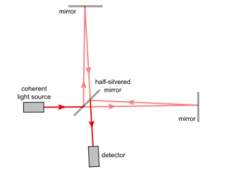
The light
path through a Michelson interferometer. The two light rays with a common
source combine at the half-silvered mirror to reach the detector. They may
either interfere constructively (strengthening in intensity) if their light
waves arrive in phase, or interfere destructively (weakening in intensity) if
they arrive out of phase, depending on the exact distances between the three
mirrors.
Interferometry
makes use of the principle of superposition to combine waves in a way that will
cause the result of their combination to have some meaningful property that is
diagnostic of the original state of the waves. This works because when two
waves with the same frequency combine, the resulting pattern is determined by
the phase difference between the two waves—waves that are in phase will undergo
constructive interference while waves that are out of phase will undergo
destructive interference. Most interferometers use light or some other form of
electromagnetic wave.[2]:3–12
Related Topics