Chapter: Basic Radiology : The Physical Basis of Diagnostic Imaging
Magnetic Resonance Imaging
MAGNETIC
RESONANCE IMAGING
The technique called nuclear
magnetic resonance, developed by physicists in the 1940s, was first utilized
for imaging the human body in the late 1970s. The nuclei of some atoms
(no-tably hydrogen nuclei in the body) have a fundamental angular momentum
called spin, which causes them to behave like tiny spinning magnets. When
placed in a uniform external mag-netic field and excited by a radio pulse tuned
to a resonant fre-quency that is proportional to the externally applied
magnetic field strength (Larmor frequency), the axis of rotation of the nuclei
will precess around the applied magnetic field direction in a similar fashion
to the precession of a leaning gyroscope or top about the gravitational field
direction (Figure 2-5). This precession can be detected, because the collection
of pro-cessing magnets (protons in the body) induces an oscilla-tory voltage in
a pickup or receiver coil. This oscillation at the Larmor frequency can be
detected by connecting the pickup coil to a radio receiver, and one could
therefore, in effect, hear the protons “singing” in unison into the coil at the
Larmor frequency. This provides no imaging informa-tion; however, if the
external magnetic field is made nonuni-form in space in a known fashion (ie, a
magnetic field gradient is utilized), then protons at different locations will
precess at different frequencies, thereby creating a relation-ship between
location in the body and precessional fre-quency. With application of such a
gradient, the protons no longer sing in unison, but at different frequencies
depend-ing on their location, as in a chorus; that is, the sopranos would be
located where the magnetic field was largest and the baritones where it was
smallest. By listening to different frequencies, one could deduce from the
signal strength at a given frequency how many protons were present at the
loca-tion corresponding to that frequency. This method of imag-ing allows one
to map the density of protons in the body inthree dimensions; however, most
images are obtained and displayed as planar cross-sectional images similar to
those in CT scans and having a slice thickness of 10 mm and a ma-trix size that
is typically 128 256. For greater contrast, the proton density images may also
be weighted by the relax-ation times (T1, T2), which are measures of the
realignment times of protons with respect to the magnetic field direc-tion.
This weighting is typically accomplished by varying the radiofrequency pulse
durations and spacings in a variety of pulse sequences, the spin-echo pulse
sequence being the most commonly used.
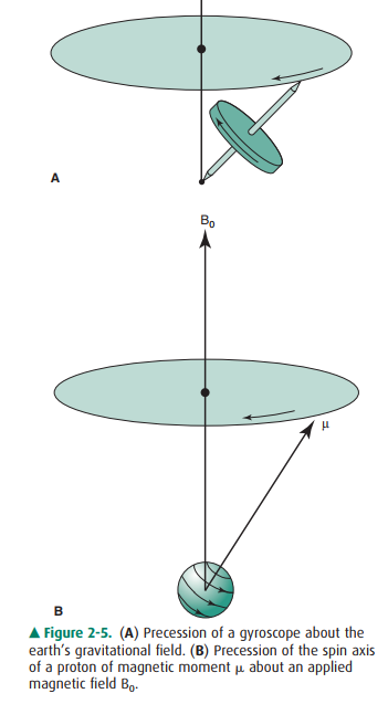
Figure 2-5. (A) Precession of a gyroscope about the earth’s gravitational field. (B) Precession of the spin axis of a proton of magnetic moment about an applied magnetic field B0.
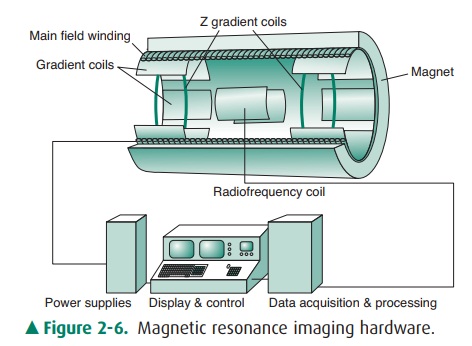
The hardware of a (nuclear)
magnetic resonance imaging machine (Figure 2-6) consists typically of a
cylindrical super-conducting coil surrounding the patient to generate a large,
static magnetic field; auxiliary coils for generating the mag-netic field
gradients; radio transmitter/receiver coils in close proximity to the patient;
electronics for radiofrequency transmitting and receiving; and a computer to
orchestrate the events and to reconstruct the spatial image from the fre-quency
spectra.
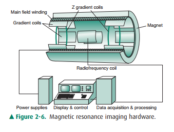
Figure 2-6. Magnetic resonance imaging
hardware.
Related Topics