Chapter: Basic Radiology : The Physical Basis of Diagnostic Imaging
Computed Tomography
Computed
Tomography
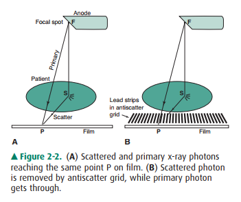
In radiography or fluoroscopy,
one is creating a shadow pic-ture or a projection of the attenuation properties
of the human body onto a plane. Thus, each ray from the source to a given point
on the film, such as ray FP in Figure 2-2, con-veys information about the sum
of the attenuation along a line in the body; that is, anatomic structures are
piled on top of each other and flattened into the radiographic image. In an
attempt to give a different perspective, one may obtain projections from two
different directions (eg, a lateral and an anteroposterior radiograph), so that
the structures that are piled on top of each other differ in each projection.
In the late 1960s a British engineer, Geoffrey Hounsfield, con-cluded that if
one obtained projection data from a sufficient number of different angles, one
could reconstruct the atten-uation properties of each volume element in the
body and display these as a cross-sectional image. This required the
computational power of a computer to accomplish, and the basic idea is
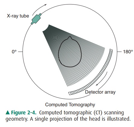
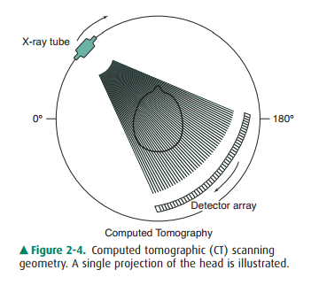
illustrated in Figure 2-4. The x-rays from a source are detected by a series of
individual detectors (rather than film) after penetrating the body, and each
detector de-fines a ray from the source through the body, thereby creat-ing a
projection. The width of the x-ray beam in the dimension perpendicular to the
page is only about 10 mm; hence, only one slice of the body in the longitudinal
direc-tion is imaged at a time.
The x-ray tube and the detector
bank are rotated 360 de-grees about the patient to obtain, for example, 720
projec-tions at 0.5-degree intervals. The computer is then able to reconstruct
a cross-sectional image of the slice of the body by dividing the slice into an
imaginary matrix. In a matrix of 512 x 512 pixels in the transverse plane, each
pixel represents an area of about 0.5 x 0.5 mm in a 25-cm diameter body. The
computer assigns a numerical value to each pixel, which rep-resents the amount
of attenuation contributed by the volume element of the body represented by
that pixel, and these numbers are converted into a gray-scale image for
viewing. In an axial scan series, after one slice is completed, the patient is
advanced via a motorized couch by 10 mm in order to image the adjacent slice,
and up to 30 slices (images) may be done to reconstruct the anatomy over a
30-cm length of the patient. Newer scanners, called helical (or spiral) CT
scanners, use a continuous advance of the patient through the scan beam rather
than the stepping couch motion utilized in axial scans, and axial slices are
reconstructed by interpolation of data into the slice from a complete rotation.
Multislice helical scanners with subsecond rotation times have been developed
that collect data for reconstruction of several slices in each rotation; thus,
a 30-cm length of patient anatomy can be im-aged in 15 seconds or less.
Figure 2-4. Computed tomographic (CT) scanning geometry. A single projection of
the head is illustrated.
Related Topics