Chapter: Mechanical : Heat and Mass Transfer : Phase Change Heat Transfer and Heat Exchangers
LMTD Method
LMTD METHOD :
Expression
for Log Mean Temperature Difference - Its Characteristics
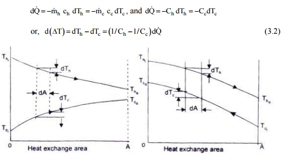
Fig. represents a
typical temperature distribution which is obtained in heat exchangers. The rate
of heat transfer through any short section of heat exchanger tube of surface
area dA is: dQ = U dA(Th –Tc cools and the cold fluid is heated in the direction
of increasing area. therefore, we may write

For a counter flow heat
exchanger, the temperature of both hot and cold fluid decreases in the
direction of increasing area, hence

Fig. 3.9 Parallel flow
and Counter flow heat exchangers and the temperature distribution with length
Integrating equations
(3.1) and (3.2) between the inlet and outlet. and assuming that the specific
heats are constant, we get
The positive sign
refers to parallel flow exchanger, and the negative sign to the counter
(The assumption that U
is constant along the heat exchanger is never strictly true but it may be a
good approximation if at least one of the fluids is a gas. For a gas, the
physical properties do not vary appreciably over moderate range of temperature
and the resistance of the gas film is considerably higher than that of the
metal wall or the liquid film, and the value of the gas film resistance
effectively determines the value of the overall heat transfer coefficient U.)
It is evident from
Fig.1 0.9 that for parallel flow exchangers, the final temperature of fluids
lies between the initial values of each fluid whereas m counter flow exchanger,
the temperature of the colder fluid at exit is higher than the temperature of the
hot fluid at exit. Therefore, a counter flow exchanger provides a greater
temperature range, and the LMTD for a counter flow exchanger will be higher
than for a given rate of mass flow of the two fluids and for given temperature
changes, a counter flow exchanger will require less surface area.
Special
Operating Conditions for Heat Exchangers
(i) Fig.
3.7a shows temperature distributions for a heat exchanger (condenser) where the
hot fluid has a much larger heat capacity rate, C h = m h ch
than that of cold fluid, Cc =m c cc and therefore, the temperature of the hot fluid
remains almost constant throughout the exchanger and the temperature of the
cold fluid increases. The LMTD, in this case is not affected by whether the
exchanger is a parallel flow or counter flow.
(ii) (ii)
Fig. 3.7b shows the temperature distribution for an evaporator. Here the cold
fluid expenses a change in phase and remains at a nearly uniform temperature Cc
- > inf. The same effect would be achieved without phase change if Cc >> Ch and the LMTD will remain the same for both
parallel flow and counter flow exchangers.
(iii)
(iii) In a counter flow exchanger, when
the heat capacity rate of uoth the fluids are equal, Cc = Ch , the temperature difference is the same
all along the length of the tube. And in that case, LMTD should be replaced by DTa DTb,
and the temperature profiles of the two fluids
along Its length would be parallel straight lines.
along Its length would
be parallel straight lines.)
LMTD for Cross-flow Heat Exchangers :
LMTD given by Eq (10.6)
is strictly applicable to either parallel flow or counter flow exchangers. When
we have multipass parallel flow or counter flow or cross flow exchangers, LMTD
is first calculated for single pass counter flow exchanger and the mean
temperature difference is obtained by multiplying the LMTD with a correction
factor F which takes care of the actual flow arrangement of the exchanger. Or,

The
correction factor F for different flow arrangements are obtained from charts
given.
Related Topics