Chapter: Mechanical : Heat and Mass Transfer : Phase Change Heat Transfer and Heat Exchangers
Classification of Heat Exchangers
Classification of Heat Exchangers
Heat exchangers are
generally classified according to the relative directions of hot and cold
fluids:
(a) Parallel
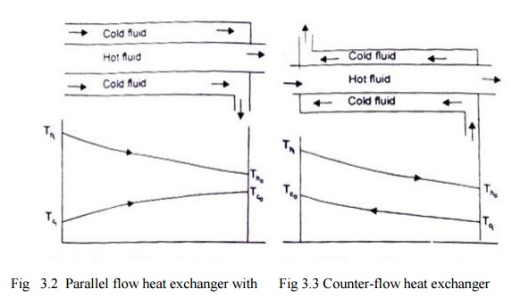
Flow –the hot and cold fluids flow in the same direction. Fig 3.2 depicts such
a heat exchanger where one fluid (say hot) flows through the pipe and the other
fluid (cold) flows
through the annulus.
(a) (b)
Counter Flow –the two fluids flow through the pipe but in opposite directions.
A common type of such a heat exchanger is shown in Fig. 3.3. By comparing the
temperature distribution of the two types of heat exchanger

Fig
3.2 Parallel flow heat exchanger with Fig
3.3 Counter-flow heat exchanger
temperature
distribution with
temperature distribution
we find that the
temperature difference between the two fluids is more uniform in counter flow
than in the parallel flow. Counter flow exchangers give the maximum heat
transfer rate and are the most favoured devices for heating or cooling of
fluids.
When the two fluids
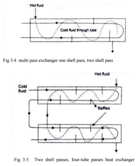
flow through the heat exchanger only once, it is called one-shell-pass and
one-tube-pass as shown in Fig. 3.2 and 3.3. If the fluid flowing through the
tube makes one pass through half of the tube, reverses its direction of flow,
and makes a second pass through the remaining half of the tube, it is called
'one-shell-pass, two-tube-pass' heat exchanger,fig 3.4. Many other possible
flow arrangements exist and are being used. Fig. 10.5 depicts a
'two-shell-pass, four-tube-pass' exchanger.
(b) Cross-flow
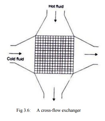
- A cross-flow heat exchanger has the two fluid streams flowing at right angles
to each other. Fig. 3.6 illustrates such an arrangement An automobile radiator
is a good example of cross-flow exchanger. These exchangers are 'mixed' or
'unmixed' depending upon the
mixing or not mixing of
either fluid in the direction transverse to the direction of the flow stream
and the analysis of this type of heat exchanger is extremely complex because of
the variation in the temperature of the fluid in and normal to the direction of
flow.
(d)
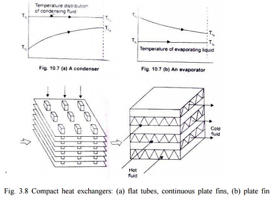
Condenser and Evaporator - In a
condenser, the condensing fluid temperature remains almost constant throughout
the exchanger and temperature of the colder fluid gradually increases from the
inlet to the exit, Fig. 3.7 (a). In an evaporator, the temperature of the hot
fluid gradually decreases from the inlet to the outlet whereas the temperature
of the colder fluid remains the same during the evaporation process, Fig.
3.7(b). Since the temperature of one of the fluids can be treated as constant,
it is immaterial whether the exchanger is parallel flow or counter flow.
(e)
Compact Heat Exchangers - these devices have close arrays of finned tubes or
plates and are typically used when atleast one of the fluids is a gas. The
tubes are either flat or circular as shown in Fig. 10.8 and the fins may be
flat or circular. Such heat exchangers are used to a chieve a very large (³700 m2/mJ) heat transfer surface area per
unit volume. Flow passages are typically small and the flow is usually laminar.

Fig
3.5: Two shell passes, four-tube passes heat exchanger (baffles increases the
convection coefficient of the shell side fluid by inducing turbulance and a
cross flow velocity component)

Fig
3.6: A cross-flow exchanger

Fig. 3.8 Compact heat
exchangers: (a) flat tubes, continuous plate fins, (b) plate fin (single pass)
Related Topics