Chapter: VLSI Design : Circuit Characterization and Simulation
Interconnect Simulation
INTERCONNECT SIMULATION
1. The classical
long-channel Pao and Sah model
The
Pao-Sah model, published in 1966, was the first advanced long channel MOSFET
model to be developed. While it retained the GCA, it didn’t invoke the
depletion approximation and permitted carrier transport in the channel by both
drift and diffusion current.
The
formulation of the drain current equation is therfore general, but as a result
requires numerical integration in two dimensions, which limits its application
in CAD tools.
Approximations:
i .
Gradual Channel Approximation is used. ii . Constant mobility is assumed.
iii .
Uniform substrate doping is considered.
Advantages:
i . It is
physically based.
ii . It
gives a continuous representation of the device characteristics from weak to
strong inversion even to the saturation mode of operation.
Disadvantages:
i. It
requires excessive computational requriments since it requires numerical
integration in two dimension, rendering it unsuitable to be used for circuit
CAD.
2. The charge-sheet
based models
The
limited practical utility of the Pao-Sah model motivated a search for an
approximate advanced analytical model, that is still accurate over a wide range
of operating conditions.
The charge
sheet model, introduced separately by Bacarani and Brews in 1978, has become
the most widely adopted long channel MOSFET model that is accurate over the
entire range of inversion.
In this
model the inversion layer is supposed to be a charge sheet of infinitesimal
thickness (charge sheet approximation).
The
inversion charge density Qi can then be calculated in terms of the surface
potential ψs. The drain current is then expressed in terms of the surface
potential at the source and drain boundaries of the channel.
Approximations:
i .
Gradual Channel Approximation is used.
ii
. The mobility is assumed to be proportional to the
electric field and is constant with position along the channel.
iii
. Uniform substrate doping is considered.
Advantages:
i . It is
physically based.
ii . It
gives a continuous representation of the device characteristics from weak to
strong inversion even to the saturation mode of operation.
ii . The
charge sheet approximation introduces negligibly small error, and it is more computationally
efficient than the classical model.
Disadvantages:
i . The
boundary surface potentials cannot be expressed explicitly in terms of the bias
voltages applied to the device, but must be found by a numerical process.
ii . The
model is not valid in depletion or accumulation.
Different
approaches have been introduced to circumvent this disadvantage. In it is shown
that accurate numerical solutions for these surface potentials can be obtained
with negligible computation time penalty.
In the
surface potentials are computed using cubic splines functions. In the implicit
equation including the surface potential is replaced by an approximate
function.
Although
all of these approaches have given good results, they have neglected the effect
of the interface trap charge which is important in determining the subthreshold
characteristics of the device, namely the subthreshold swing (the gate voltage
swing needed to reduce the current by one decade).
3. Bulk Charge Model
The Bulk
Charge model also known as variable depletion charge model, was developed in
1964, describes the MOSFET drain current only in strong inversion but of course
has less computational requirements.
Approximations :
i . Drift
current component only is considered
ii .
Constant surface potential is assumed
iii
. Id considered zero below threshold
Advantages :
i . Less
computational time than the charge sheet model
Disadvantages :
i . The
subthreshold region not defined
4. Square law model
This
model has great popularity, when a first estimate to device operation, or
simulating a circuit with a large number of devices is required. This model is
obtained from the bulk charge model, on the assumption that VDS <<
2φf+VBS .
i . Drift
current component only is considered ii . Constant surface potential is assumed
iii
. Id considered zero below threshold
iv . VDS
<< 2φf+VBS
Advantages :
i . Very
small computational time than any other model ii . Suitable for hand
calculations
Disadvantages :
i . The
subthreshold region is not defined
ii .
Overestimates the drain current in saturation region
Approximate models
There
exists a large number of introduced approximate models. All of these models
originate from Brews' charge sheet model, where approximations to the surface
potentials in various operating regions of the device have been used.
This
leads to different current equations each valid only in a specific region. The
resulting equations are then empirically joined using different mathematical
conditions of continuity.
Advantages:
i . They
have good accuracy in the desired region of operation.
ii . They
are very efficient from the point of view of computational time.
Disadvantages:
i . The
error increases in the transition regions between different modes of
operations. ii . They include many non-physical fitting parameters.
5. Modified charge
sheet model
The last
discussed MOSFET models, have a common illness, no interface charges are
included which play a great role in subthreshold region. So a modified model to
the charge sheet model, which include the effect of interface charges is
carried out in ICL, and will be presented now. The derivation begins by
rewriting equation (2.3.1) in the following form :
I D = I
D1+ I D2 (2.3.6.1)
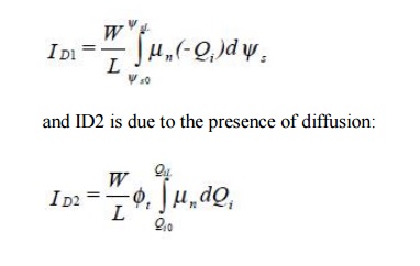
where ID1
is due to the presence of drift:

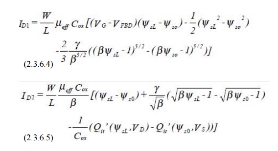
after
mathematical manipulation and following the same approximations as charge sheet
model we reach the following drain current equations:

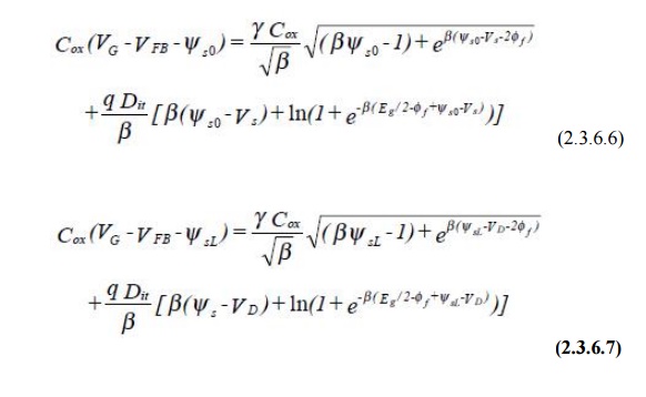
where ψs0
is the surface potential at the source end of the channel, ψsL is the surface
potential at the drain end of the channel, both are referred to the bulk. And
their values are computed from the following two implicit equations.


Related Topics