Chapter: Embedded and Real Time Systems : Computing Platform and Design Analysis
Important questions and answers: Computing Platform and Design Analysis
COMPUTING PLATFORM AND DESIGN
ANALYSIS
1. Differentiate synchronous communication and
iso-synchronous communication.
Synchronous communication
When a
byte or a frame of the data is received or transmitted at constant time
intervals with uniform phase difference, the communication is called
synchronous communication.
Iso-synchronous communication
Iso-synchronous
communication is a special case when the maximum time interval can be varied.
2. What are the two characteristics of synchronous
communication?
Bytes
maintain a constant phase difference
The clock
is not always implicit to the synchronous data receiver.
3. What are the three ways of communication for a
device?
Iso-synchronous
communication
synchronous
communication
Asynchronous
communication
4. Expand a) SPI b) SCI
SPI—serial
Peripheral Interface
SCI—Serial
Communication Interface
5. Define software timer.
This is
software that executes and increases or decreases a count variable on an
interrupt from a timer output or form a real time clock interrupt. A software
timer can also generate interrupt on overflow of count value or on finishing
value of the count variable.
6. What is I2C?
I2C is a
serial bus for interconnecting ICs .It has a start bit and a stop bit like an
UART. It has seven fields for start,7 bit address, defining a read or a write,
defining byte as acknowledging byte, data byte, NACK and end.
4. What are the bits in I2C corresponding to?
It has
seven fields for start,7 bit address, defining a read or a write, defining byte
as acknowledging byte, data byte, NACK and end
5. What is a CAN bus? Where is it used?
CAN is a
serial bus for interconnecting a central Control network. It is mostly used in
automobiles.
It has fields for bus arbitration bits, control bits for address and data
length data
bits, CRC
check bits, acknowledgement bits and ending bits.
6. What is USB? Where is it used?
USB is a
serial bus for interconnecting a system. It attaches and detaches a device from
the network. It uses a root hub. Nodes containing the devices can be organized
like a tree structure. It is mostly used in networking the IO devices like
scanner in a computer system.
7. What are the features of the USB protocol?
A device
can be attached, configured and used, reset, reconfigured and used, share the
bandwidth with other devices, detached and reattached.
8. Explain briefly about PCI and PCI/X buses.
PCI and
PCI/X buses are independent from the IBM architecture .PCI/X is an extension of
PCI and support 64/100 MHZ transfers. Lately, new versions have been introduced
for the PCI bus architecture.
9. Why are SPCI parallel buses important?
SPCI
serial buses are important for distributed devices. The latest high speed
sophisticated systems use new sophisticated buses.
10. What is meant by UART?
UART
stands for universal Asynchronous Receiver/Transmitter.
UART is a
hardware component for translating the data between parallel and serial
interfaces.
UART does
convert bytes of data to and from asynchronous start stop bit.
UART is
normally used in MODEM.
11. What does UART contain?
A clock
generator.
Input and
Output start Registers
Buffers.
Transmitter/Receiver
control.
12. What is meant by HDLC?
HDLC stands
for “High Level Data Link Control”.
HDLC is a
bit oriented protocol.
HDLC is a
synchronous data Link layer.
13. Name the HDLC’s frame structure?

14. List out the states of timer?
There are
eleven states as follows
Reset
state
Idle
state
Present
state
Over flow
state
Over run
state
Running
state
Reset
enabled state / disabled
Finished
state
Load
enabled / disabled
Auto
reload enabled / disabled
Service
routine execution enabled / disabled
15. Name some control bit of timer?
Timer
Enable
Timer
start
Up count
Enable
Timer
Interrupt Enable
16. What is meant by status flag?
Status
flag is the hardware signal to be set when the timer reaches zeros.
17. List out some applications of timer devices?
Real Time
clock
Watchdog
timer
Input
pulse counting
TDM
Scheduling
of various tasks
18. State the special features on I2C?
Low cost
Easy
implementation
Moderate
speed (upto 100 kbps).
19. What are disadvantages of I2C?
Slave
hardware does not provide much support
Open
collector drivers at the master leads to be confused
20. What are the two standards of USB?
USB 1.1
USB 2.0
21. Draw the data frame format of CAN?

22. What is the need of Advanced Serial High Speed
Buses?
If the
speed in the rate of ‘Gigabits per second’ then there is a need of Advanced
Serial
High
Speed Buses.
23. What is meant by ISA?
ISA
stands for Industry standard Architecture.
Used for
connecting devices following IO addresses and interrupts vectors as per
IBM pc
architecture.
24. What is meant by PCI-X?
PCI X
offers more speed over PCI.
30 times
more speed than PCI.
25. Define CPCI?
CPCI
stands for Compact peripheral component Interfaces.
CPCI is
to be connected via a PCI.
CPCI is
used in the areas of Telecommunication Instrumentation abd data communication
applications.
26. Define half-duplex communication.
Transmission
occurs in both the direction, but not simultaneously.
27. Define full duplex communication.
Transmission
occurs in both the direction, simultaneously
28. Define Real Time Clock (RTC)?
Real time
clock is a clock which once the system stats does not stop and cant be reset
and its count value cant be reloaded.
29. Define Time-out or Time Overflow?
A state
in which the number of count inputs exceeded the last acquirable value and on
reaching that state, an interrupt can be generated.
30. Why do we need at least one timer in an ES?
The
embedded system needs at least on timer device. It is used as a system clock.
1. Explain the parallel port
devices. Parallel Port I/O devices
In this
communication any number of ports could be connected with the device and the
data communication is bidirectional in nature.
Single
Bit Input and Output
Parallel Port Single Bit Input
Parallel Port Single Bit Output
Parallel
Port input and Output
Parallel Port Input
Parallel Port Output
Diagrams:
Parallel input port, output port and a
bidirectional port for connecting the device
The handshaking signals when used by the I/O ports.

Characteristics taken into
consideration when interfacing a device port.
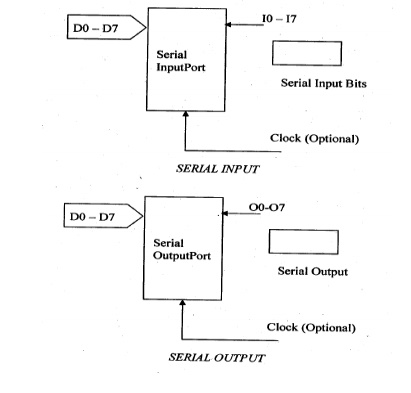
Synchronous Serial I/O devices
Synchronous
Serial communication is defined as a Byte or a Frame of data is transmitted or
received at constant time intervals with uniform phase differences.
Synchronous Serial Input Devices
.Synchronous Serial Output Devices
2. Explain
the sophisticated interfacing features in device ports.
Schmitt trigger
Data Gate
HSTL,SSTL
XCITE
Multigigabyte Transceivers
SerDes
Multiple I/O standards
PCS
PMA
3. Explain
the types of UART
UART - Universal Asynchronous Receiver Transmitter
USART Universal Synchronous Asynchronous Receiver
Transmitter
Synchronous Serial Transmission
Synchronous
serial transmission requires that the sender and receiver share a clock with
one another, or that the sender provides a strobe or other timing signal so
that the receiver knows when to "read the next bit of the data. A form of
synchronous transmission is used with printers and fixed disk devices in that
the data is sent on one set of wires while a clock or strobe is sent on a
different wire. Printers and fixed disk devices are not normally serial devices
because most fixed disk interface standards send an entire word of data for
each clock or strobe signal by using a separate wire for each bit of the word.
Asynchronous Serial Transmission
Asynchronous
transmission allows data to be transmitted without the sender having to send a
clock signal to the receiver. Instead the sender and receiver must agree on
timing parameters in advance and special bits are added to each word which is
used to synchronize the sending and receiving units.
When a word is given to the UART for Asynchronous
transmissions, a bit called the "Start Bit" is added to the beginning
of each word that is to be transmitted.
After the Start Bit, the individual bits of the
word of data are sent, with the Least Significant Bit (LSB) being sent first.
Each bit in the transmission is transmitted for
exactly the same amount of time as all of the other bits and the receiver look at
the wire at approximately through the assigned to each bit to determine if the
bit is a 0 or 1.
The sender does not know when the receiver has
"looked" at the value of the bit. The sender only knows when the
clock says to begin transmitting the next bit of the word.
When the entire data word has been sent, the
transmitter may add a Parity Bit that the transmitter generates.
The Parity Bit may be used by the receiver to
perform simple error checking. Then at least one Stop Bit is sent by the
transmitter.
When the
receiver has received all of the bits in the data word. It may check for the
Parity Bits (both sender and receiver must agree on whether a Parity Bit is to
be used) and then the receiver looks for a Stop Bit. If the Stop Bit does not
appear when it is supposed to the UART considers the entire word to be garbled
and will report a Framing Error to the host processor when the data word is
read. The usual cause of a Framing Error is that the sender and receiver clocks
were not running at the same speed, or that the signal was interrupted.
Regardless
of whether that data was received correctly or not, the UART automatically
discards the Start, Parity and Stop bits. If the sender and receiver are
configured identically, these bits are not passed to the host.
4. Describe in detail about
Synchronous, ISO-Synchronous and Asynchronous communication for serial device.
Synchronous
In this
means of communication, byte or frame of data received and transmitted at
constant time intervals with uniform phase differences. Bits of a data frame
are sent in a fixed maximum time intervals. Handshaking between sender and
receiver is not provided during communication.
Example
Frames
sent over LAN.
Characteristics
The main
features of the synchronous communication are
Bytes maintain a constant phase difference. No
sending of bytes at random time intervals.
A clock must be present at transmitter to send the data Moreover, the
clock information is sent to the receiver (i.e.) it is not always implicit to
the receiver.
Communication Protocols used
Most often synchronous serial communication is useil for
Data is transmission between physical devices.
It can be complex and has to be as per the communication
Protocol followed.
Example., HDLC (High Level Data Link Control)
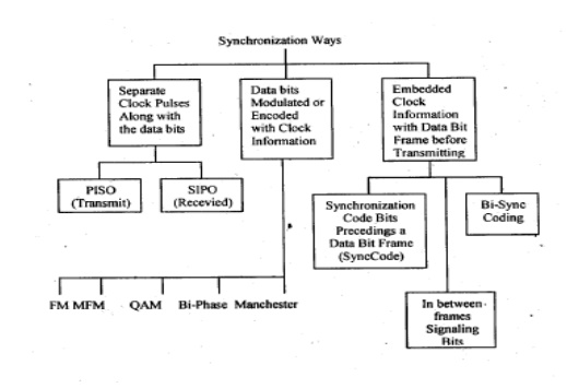
Synchronization ways
Ten ways by which the synchronous signals with the
clocking info transmitted from transmitter to the receiver are as shown below.

Iso-Synchronous
Iso-synchronous
communication is a special case of synchronous communication. In contrast with
the synchronous communication where bits of data frame are sent in a fixed
maximum time interval, the iso=synchronous communication may have varied
maximum time intervals.
Asynchronous
In the
asynchronous communication a Byte or a Frame of data is received or sent at
variable time intervals with phase difference.
The data
is sent as a series of bits. A shift register (in either hardware or software)
is used to serialize each information byte into the series of bits which are
then sent on the wire using an I/O port and a bus driver to connect to the
cable
Characteristics
Bytes or Frames of data is sent or received at variable time intervals.
Handshaking between sender and receiver is provided during
communication.
A clock is needed at the transmitter to send the data'
The clock data is not sent to the receiver (i.e) it is always ' implicit
to the receiver.
5. Give some Examples of Internal
Serial Communication
Common
USART like Device in 8051
There will be a common USART like hardware device
in 805 1.
USART - Universal Synchronous and Asynchronous.
Receiver and Transmitter
It is also called as SI (Serial Interface)
Features
SCON - Saves Control and status flags in SI
SFR - Special Function Register
SBUF - Serial Buffer
SI Operates in two modes
Half Duplex Synchronous mode of operation
Full Duplex Asynchronous mode of operation
SPI and
SCI: Serial Peripheral Interface (SPl)
It has full duplex feature for asynchronous
communication
It has a feature of programmable rates for clock
bits.
It is also programmable for defining the –instance
of the occurrence to negative and positive edges within intervals of bits.
Devices selection is also programmable
Serial Communication Interfaces
(SC I)
UART asynchronous (SCD baud rates are same as SPI
but not programmable.
Communication is in full duplex
Characteristics
A port device may have multi byte data input buffer
and output buffer
A port may have a DDR.
Port may have LSTTL driving capability and port
loading capability
Multiple functionality in ports
Iso-synchronous
communication is a special case of synchronous communication. In contrast with
the synchronous communication where bits of data frame are sent in a fixed
maximum time interval, the iso-synchronous communication may have varied
maximum time intervals.
Protocol
Most
often synchronous serial communication is used for
Data is transmission between physical devices.
It can be complex and has to be as per the
communication
Protocol followed.
Example., HDLC (High Level Data Link Control)
6. Explain
Memory & IO Devices Interfacing (Memory Mapped I/O)
I/O operations are interpreted differently
depending on the viewpoint taken and place different requirements on the level
of understanding of the hardware details.
From the perspective of a system software
developer, I/O operations imply communicating with the device, programming the
device to initiate an I/O request, performing actual data transfer between the
device and the system, and notifying the requestor when the operation
completes. The system software engineer must understand the physical
properties, such as the register definitions, and access methods of the device.
Locating the correct instance of the device is part of the device
communications when multiple instances of the same device are present.
The system engineer is also concerned with how the
device is integrated with rest of the system. The system engineer is likely a
device driver developer because the system engineer must know to handle any
errors that can occur during the I/O operations.
From the perspective of the RTOS, I/O operations
imply locating the right device for the I/O request, locating the right device
driver for the device, and issuing the request to the device driver. Sometimes
the RTOS is required to ensure synchronized access to the device.
The RTOS must facilitate an abstraction that hides
both the device characteristics and specifics from the application developers.
From the perspective of an application developer, the goal is to find a simple,
uniform, and elegant way to communicate with all types of devices present in
the system. The application developer is most concerned with presenting the
data to the end user in a useful way.
The combination of I/O devices, associated device
drivers, and the I/O subsystem comprises the overall I/O system in an embedded
environment.
The purpose of the I/O subsystem is to hide the
device-specific information from the kernel as well as from the application
developer and to provide a uniform access method to the peripheral I/O devices
of the system.
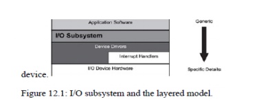
This section discusses some fundamental concepts
from the Perspective of the device driver developer. Figure 12.1 illustrates
the I/O subsystem in relation to the rest of the system in a layered software model.
As Shown, each descending layer adds additional detailed information to the
architecture needed to manage a given device. Figure 12.1: I/O subsystem and
the layered model.

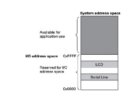
In memory-mapped I/O, the device address is part
of the system memory address space. Any machine instruction that is encoded to
transfer data between a memory location and the processor or between two memory
locations can potentially be used to access the I/O device.
The I/O device is treated as if it were another memory location. Because
the I/O address space occupies a range in the system memory address space, this
region of the memory address space is not available for an application to use.
Figure 12.3: Memory-mapped I/O. The memory-mapped
I/O space does not necessarily begin at offset 0
in the system address space, as illustrated in Figure

Related Topics