Chapter: mechanical : Engineering Graphics
Importance of Engineering Graphics
IMPORTANCE OF ENGINEERING GRAPHICS
In Engineering Profession, it is very essential that the Engineers and Craftsmen are able to communicate their ideas and facts with each other clearly and without ambiguity. The verbal communication may be hopelessly inadequate. The written communication, on the other hand may be very inefficient, lengthy and boring to create accurate mental and physical impression of an item in the mind of the reader.
The Engineering Drawing, which is a Graphical Communication of an accurate and unambiguous description of an object, has proved to be an efficient communication method. It is a means of organizing and presenting precise technical directions for items to be produced for the consumers.
Engineering Drawing can supply all the information needed with the exactness and details required. It is therefore, one of the principal functions of drawing to convey ideas from the design engineer to the fabricator. Hence, the skill to interpret and construct engineering sketches and drawings is of paramount importance.
The engineer may convey his ideas by one or more of the three basic types of projections namely; Orthographic Projection, Oblique Projection or Perspective Projection, depending upon the purpose of the drawing and the person to whom he wishes to convey his ideas. Certain professional areas have different nomenclature such as Machine Drawing, Architectural Drawing, and Structural Drawing.
RAWING INSTRUMENTS AND SHEET LAYOUT
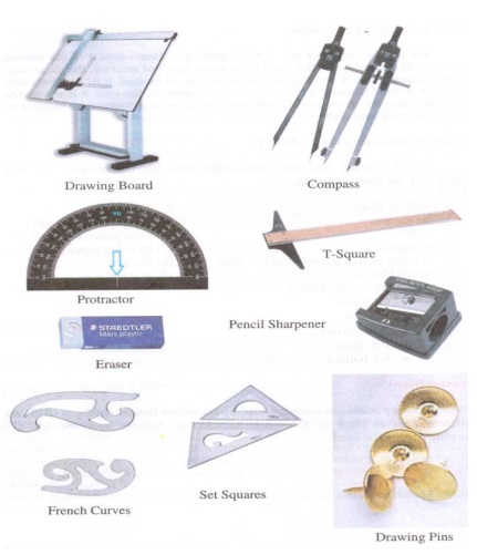

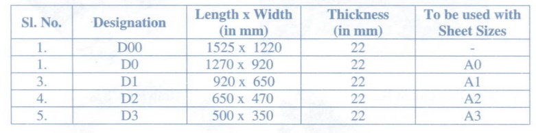
DRAWING BOARD SIZE
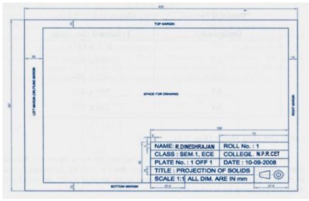
DRAWING SHEET LAYOUT
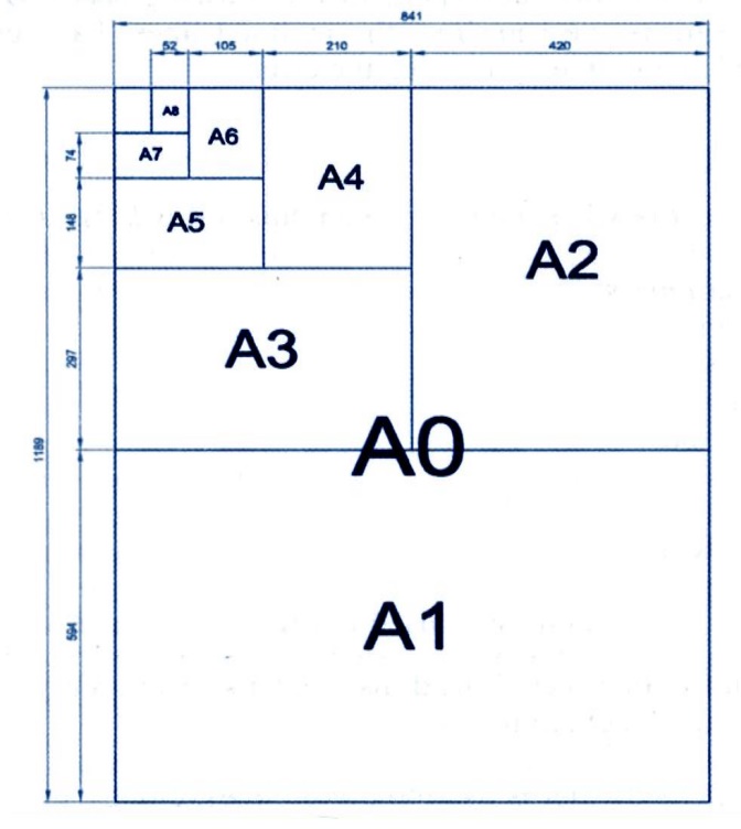
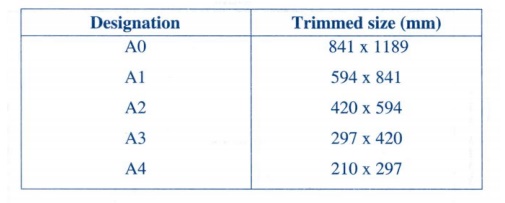
DRAWING SHEET SIZE
TITLE BLOCK OF DRAWING SHEET
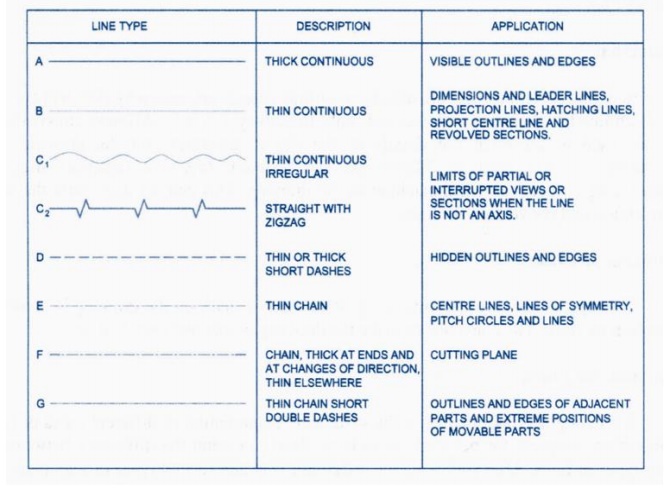
LINES, LETTERING AND DIMENSIONING
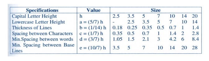
SPECIFICATION OF “A” TYPE LETTERING:
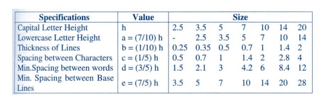
SPECIFICATION OF “B” TYPE LETTERING:
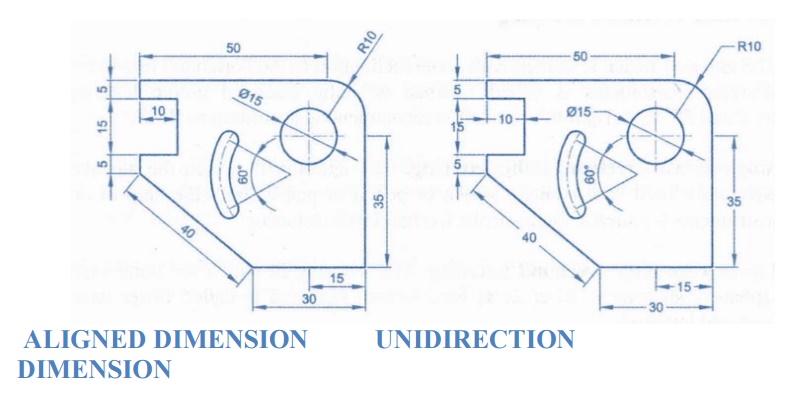
ALIGNED DIMENSION UNIDIRECTION DIMENSION
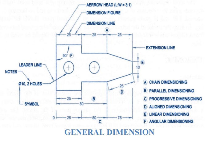
GENERAL DIMENSION
GEOMETRICAL CONSTRUCTIONS
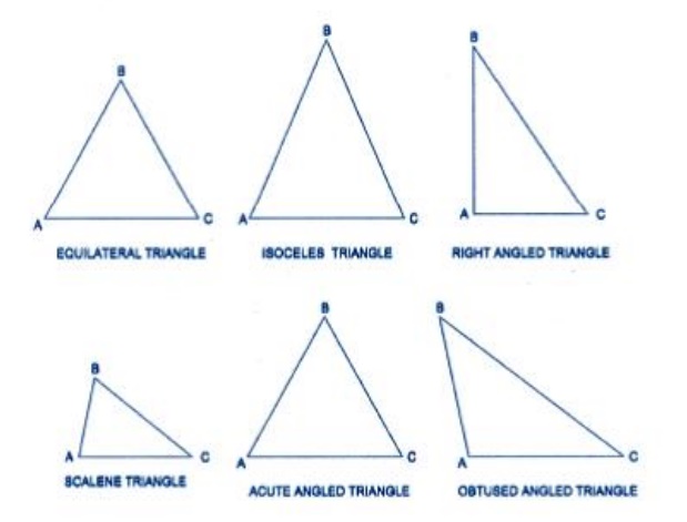
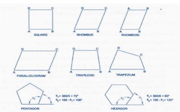
The construction of plane figures such as triangle, circles, and polygons etc., used in plane geometry is called geometrical constructions.
(i) A Pentagon is that which has five equal sides.
(ii) A hexagon is that which has six equal sides.
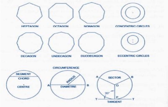
(iii) A heptagon is that which has seven equal sides.
(iv) An octagon is that which has eight equal sides.
(v) A nonagon is that which has nine equal sides.
(vi) A decagon is that which has ten equal sides.
(vii) An UN decagon is that which has eleven equal sides.
(viii) A duo decagon is that which has twelve equal sides.
(ix) A diagonal of a polygon is the line joining any two of its angular points.
Bisect the line, Bisect the Arc, and Draw the perpendicular line
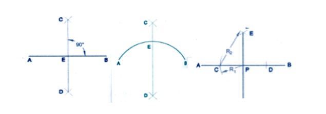
To divide a line into any number of equal part and Bisect angle between two lines
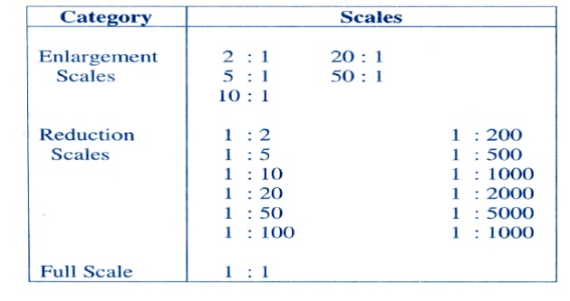
SCALE
Scale = Size of Drawing / Actual Size

Related Topics