Chapter: mechanical : Engineering Graphics
Important Keypoints and Notation in Engineering Graphics
KEYPOINTS & NOTATIONS
IMPORTANT NOTATION IN ENGINEERING GRAPHICS
HP means the Horizontal Plane
VP means the Vertical Plane
FV means the Front View
TV means the Top View
SV means the Side View
STV means the Sectional Top View
GR means the Ground
TL means the True Length
CP means the Cutting Plane
PPP means the Picture Plane for Perspective Projection.
KEY POINTS ABOUT THE PROJECTIONS OF POINTS:
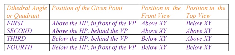
1. The front view and the top view of a point are always on the same vertical line.
2. The distance of the front view of a point from the XY line is always equal to the distance of the given point from the HP.
3. If a given point is above the Hp, its front view is above the XY line. If the given point is below the Hp, its front view is below the XY line.
4. The distance of the top view of a point from the XY line is always equal to the distance of the given point from the VP.
5. If a given point is in front of the VP, its top view is below the XY line. If the given point is behind the VP, its top view is above the XY line.]
KEY POINTS ABOUT THE POSITIONS OF A POINT AND ITS PROJECTIONS:
PROJECTIONS OF A LINE INCLINED TO BOTH THE REFERENCE PLANES:
Case I:
If a straight line is projected when it is inclined at e to the HP and either parallel to the VP or inclined to the VP, then:
(i) The length in the top or plan view remains the same and
(ii) If one end point in the FV remains at constant distance from XY, the other end point will also remain at the same distance from XY, provided the
angle with the HP does not change. In other words, if point A of a straight line
AB is fixed, point B will have its front view b' on a path parallel to the XY line.
Case II:
If a straight line is projected when it is inclined at q; to the VP and either parallel to the HP or inclined to the HP, then:
(i) The length in the front view remains the same and
(ii)If one end point in the TV remains at a constant distance and if the angle from XY with the VP does not change, the other end point will also remain at the same distance from XY. In other words, if point A of a straight line AB is fixed, point B will have its top view b on a path parallel to the XY line.
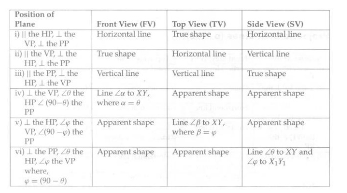
KEY POINTS TO REMEMBER ABOUT PROJECTIONS OF PLANES:
1. Plane perpendicular to one reference plane and parallel to the other (one step)
If it is parallel to the VP and perpendicular to the HP, its front view is drawn with the true shape and size and the top view is a horizontal line.
If it is parallel to the HP and perpendicular to the VP, its top view is drawn with the true shape and size and the front view is a horizontal line.
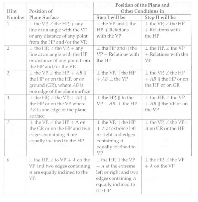
II. When a plane is perpendicular to one and inclined to the other, two steps are required to draw the projections (two steps)
Step I:
If the given plane is perpendicular to the VP and inclined to the HP, assume it to be parallel to the HP in Step I. If it is perpendicular to the HP and inclined to the VP, assume it to be parallel to the VP in Step I.
Step II:
Rotate the plane to make it inclined to one reference plane, as required, keeping it perpendicular to the other.
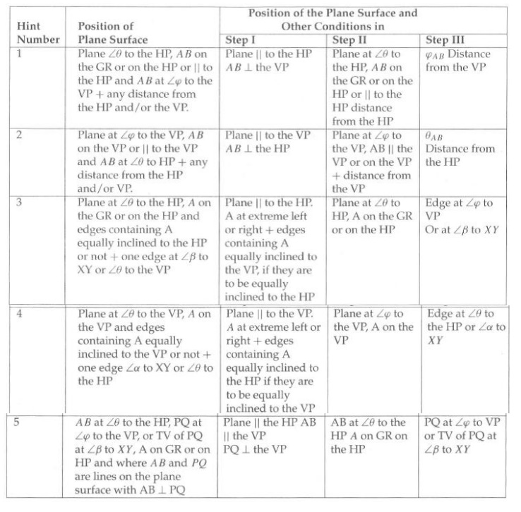
III. When a plane is inclined to both reference planes, three steps are required to draw the projections
Step I:
The plate is assumed to be parallel to the VP, perpendicular to the HP, and have one of its edges, say, AI B l, perpendicular to the HP.
Step II:
The plate is assumed to be inclined to the VP at an angle Φ, while remaining perpendicular to the HP. The other edge, say, A2B2 also remains perpendicular to the HP. As relations with the HP do not change, projection on the HP, that is, the top view, remains as a straight line and front views are at the same distance from XY as the corresponding points are from XY in Step 1.
Step III:
The plate is assumed to be rotated so that A2B2becomes AB, inclined at e to the HP. However, none of the lines or points changes their relations with the VP. Hence, in the front view the shape does not change and the distances of various points from the XY line in the top view remain the same in Step II and Step III.
THE POSITION OF THE PLANE TWO STEP PROBLEM:
THE POSITION OF THE PLANE FOR THREE-STEP PROBLEMS:
Projections of Solids:
For drawing projections of solids, one has to frequently draw projections of lines either parallel to the HP or the VP and inclined to the other with an angle that is between 0 to 90°.Similarly, sometimes, the projections of plane surfaces Perpendicular to one and inclined to the other are required to be drawn.
IMPORTANCE POINTS OF PROJECTION OF LINES
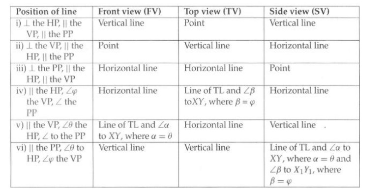
Further, it may be recollected that the relations of the original point, line, or plane with the HP are the relations of its FV or SV with the XY line. Similarly, those with the VP are the relations of its TV with the XY line or it’s SV with the X IY1 line.
IMPORTANCE POINTS OF PROJECTION OF PLANES:
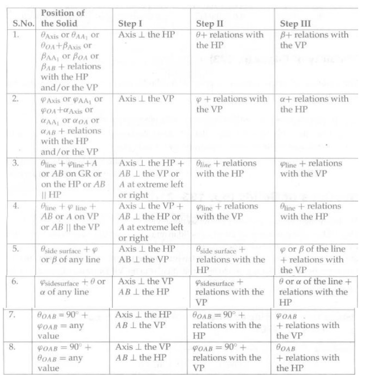
PROJECTIONS OF SOLIDS WITH THE AXIS PARALLEL TO ONE AND INCLINED TO THE OTHER REFERENCE PLANE:
The projections of a solid with its axis parallel to the VP and inclined to the HP or parallel to the HP and inclined to the VP cannot be drawn directly as the base of such a solid will not be parallel to anyone of the reference planes and two steps are required to draw the projections. Such problems are solved in two steps and the possible cases are listed in a table.
HINTS FOR CONDITIONS TO BE SATISFIED IN TWO-STEP PROBLEMS:
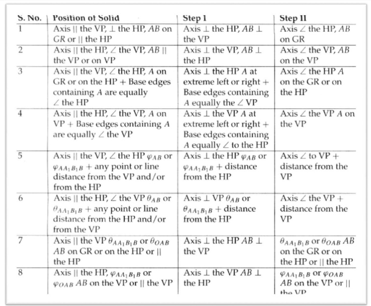
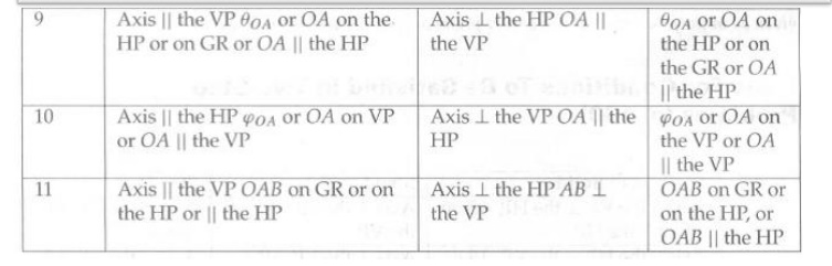
HINT FOR POSITION OF THE AXIS:
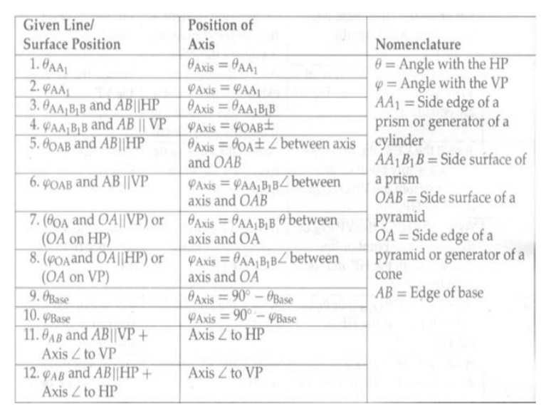
PROJECTIONS OF SOLIDS WITH THE AXIS INCLINED TO BOTH
THE HP AND THE VP (HINTS FOR CONDITIONS TO BE SATISFIED IN THE THREE-STEP PROBLEMS):
SECTION OF SOLIDS:
The following steps can be used to draw sectional views:
Step I:
Draw the projections of the given solid in an uncut condition in both the views (the FV and the STY) by thin construction lines.
Step II:
Draw the cutting plane (or the section plane) as a straight line inclined at B to the XY line in the front view if it is given to be perpendicular to the VP. Draw it inclined at B to the HP or as a straight line inclined at rp to XY in the top view, if it is given to be perpendicular to the HP and inclined at rp to the VP.
Step III:
If the solid is a cylinder or a cone, draw a number of generators intersecting the cutting plane line. Obtain their projections in the other view. Generators are lines drawn through the points on the base circle and are parallel to the axis for a cylinder or joining the apex for a cone.
Step IV:
Locate the point’s common between the cutting plane line and the surface lines of the solid. These surface lines include the base and side edges of prisms and pyramids or the generators and circular edges of cylinders and cones. Number these points as follows:
(i) Start from one end of the cutting plane, and move towards the other end naming the points on visible surface lines sequentially.
After reaching the other end, return along the cutting plane line and continue to number those points that are on hidden surface lines sequentially. In case of a hollow solid, imagine the hole as a separate solid and number the points in the usual manner.
Step V:
Project the points in the other views by drawing interconnecting projectors and intersecting the concerned surface lines.
Step VI:
Join the points obtained in Step V by continuous curved lines if the points are on a conical or a cylindrical surface. Otherwise, join them by straight lines. The apparent section is completed by drawing cross-hatching section lines within the newly cut surface.
Step VII:
Complete the projections by drawing the proper conventional lines for all the existing edges and surface boundaries.
HINT TO LOCATE THE CUTTING PLANE:
The required cutting plane can be quickly located if the following hints are kept in mind:
1. The number of comers in the true shape of a section is always equal to the number of edges of the solid that is cut by the cutting plane.
2. The true shape of a section has a configuration similar to that of its apparent section. This means:
(i) The number of edges and corners are equal.
(ii) Any pair of lines, if parallel in one, will remain parallel in the other. (iii) A rectangle in one need not be a rectangle in the other. Instead, it will be a four-sided figure with the opposite sides parallel. That is, it may be a rectangle, a Square or a parallelogram
(iv) A curved boundary in one will remain a curved boundary in the other
but a Circle need not be a circle. It may also be an ellipse.
3. A section as curve can be obtained only when the generators of a cylinder or of a cone are cut.
4. When a cutting plane cuts all the generators of a cylinder or a cone, then the true shape of the section is an ellipse.
5. When the cutting plane is inclined to the base of a cone at an angle that is equal to, greater than or less than that made by its generator with the base, then the true shape of the section is a parabola a hyperbola or an ellipse, respectively.
6. When a cutting plane cuts along the generators of a cone, then the true shape of the section is an isosceles triangle.
7. When a cutting plane cuts along the generators of a cylinder, then the true shape of the section is a rectangle.
The actual procedure to locate the cutting plane involves the following steps:
Step I:
Draw the projections of the given uncut solid in the proper position with respect to the HP and the VP by then lines.
Step II:
If the cutting plane is to be perpendicular to the VP or the HP, draw a number of trial cutting planes in the front view or in the top view, respectively. Select those cutting planes that intersect the number of edges of the solid equal to the number of corners of the true shape of the required section. If the solid is a cone or a cylinder, select the cutting plane based on Hints (4) to (7).
Step III:
Sketch the shape of the section by projecting points on one of the selected cutting planes. If the cutting plane line is inclined to the XY line, the shape of the section that will be obtained will not be the true shape and it is called an apparent section.
Step IV:
From a sketch of the true shape, find out the dependence of its dimensions on the various lines in projections, and find out whether by shifting the cutting plane the same edges and surfaces can be cut and whether the required lengths can be obtained for the true shape of the section. Accordingly, adjust the position of the cutting plane. If adjustment of dimensions is not possible, try another cutting plane and rework steps III and IV.
DEVELOPMENT OF SURFACES;
Step I:
Draw the projections of the given solid in the uncut condition using thin
lines.
Step II:
Draw the cutting plane as a line in the front or top view depending upon whether it is perpendicular to the VP or the HP. If the cut is a cylindrical or prismatic hole, it will be drawn as a circle or a polygon in the FV or the TV depending upon whether its axis is perpendicular to the VP or the HP.
Step III:
Draw a number of surface lines, particularly the ones that are intersecting the Cutting plane line and passing through the critical points as in the case of intersections of surfaces problems. For a curved solid or a curved cut, draw at least one more surface line between two adjacent critical points.
Step IV:
Locate the point’s common between the cutting plane lines and surface lines, and number them in the same manner as in Chapter 10. The edges of the base or side surfaces are also surface lines.
Step V:
Draw the development of the uncut solid and locate the positions of the surface Lines by thin lines drawn in Step III.
Step VI:
The point’s common between the cutting plane and the surface lines named in
Step IV can be located on the respective surface lines of the development at true distances from the known end points of those surface lines. If the concerned surface line does not represent the true length either in the FV or the TV, find its true length by making one view parallel to XY and transfer the cutting plane point on it. Find its true distance from one of the end points. And use this distance to plot the point in the development.
Step VII:
Join the cutting plane points in serial cyclic order in the development. If the solid is a curved one or the cutting plane is curved, join the points by curved lines, otherwise, by straight lines. The number of lines in the development will be equal to the number of formed corners, and a corner may form where the edge of the solid is cut by the cutting plane or where there is a corner in the cut. If the two points to be joined in sequence are located on edges of the same base, they should be joined by moving along existing base/v edges if the development of the lateral surface is drawn.
Step VIII:
Complete the development by drawing boundary lines by thick lines. Complete the projections by drawing proper conventional lines for all existing edges and surface boundaries.
Isometric
Projections:
Isometric and Orthographic Projections of Principal Lines
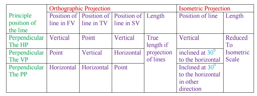
The steps for drawing isometric projections of an object are as follows:
Draw orthographic projections of the given object and enclose each view in the smallest rectangle. The sides of the rectangles should be vertical and horizontal lines only because they are supposed to be the principal lines of the enclosing box of the Object.
Step II:
Select the faces that are to be visible so that the maximum number of visible
Lines/surfaces are obtained in the isometric projection. Generally, the front face, the top face, and one side face are made visible. If the left-side view gives the maximum number of visible lines, the left face is made visible. If the right-side view gives the maximum number of visible lines, the right face is made visible.
Step III:
Correlate the projections of the various surfaces in all the views by using the Properties of projections of plane surfaces. Having co-related the projections in two views or more, points should be measured in principal directions in any two views and should be plotted in isometric projections. Coordinate distances should be reduced to isometric scale before plotting.
Step IV:
Draw all the boundaries of surfaces by proper conventional lines depending upon their visibility.
Important points in perspective projection:
i. A surface touching the PPP has its true shape and size in the perspective view.
ii. Perspective views of lines touching the PPP are of their true lengths and true inclinations.
iii. Perspective views of vertical lines are vertical lines.
iv. Perspective views of horizontal lines, parallel to each other and inclined to the PPP; converge into a single point, which is the front view of the vanishing point.
v. Perspective views of lines parallel to the PPP are parallel to the original lines.
vi. If the object is behind the PPP, the size of its perspective view will be reduced in size compared to the object. Also, the greater the distance from the PPP, the smaller the perspective.
Related Topics