Chapter: mechanical : Engineering Graphics
Projection of Straight Lines and Planes [First Angle]
PROJECTION OF STRAIGHT LINES AND PLANES [FIRST ANGLE]
Projection
of straight lines, situated in first quadrant only, inclined to both horizontal
and vertical planes – LOCATION OF TRACES ONLY. Determination of true length and
true inclinations of straight lines from the projections (not involving traces)
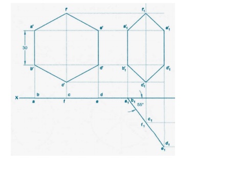
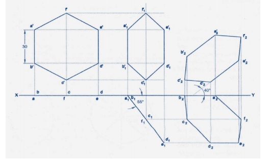
Projection of plane surfaces like rectangle, square, pentagon, hexagon, circle-
surfaces inclined to one reference plane.
PROJECTION OF LINES AND PLANES
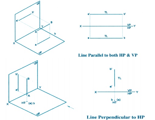
A straight line is the shortest distance
between two points. Projections of the ends of any line can be drawn using the
principles developed for projections of points. Top views of the two end points
of a line, when joined, give the top view of the line. Front views of the two
end points of the line, when joined, give the front view of the line. Both
these Projections are straight lines.
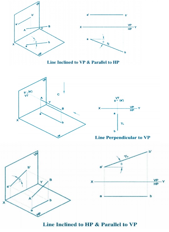
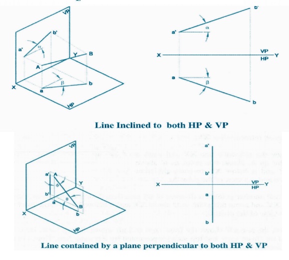
Projection of straight lines
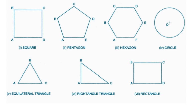
Projection of Plane Surfaces:
A plane
is a two dimensional object having length and breadth only. Its thickness is
always neglected; various shapes of plane figures are considered such as
square, rectangle, circle, pentagon, hexagon, etc.
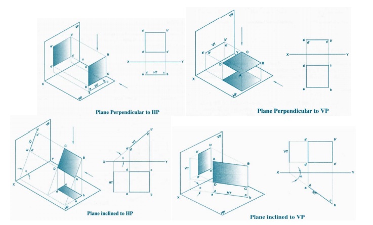
TYPES OF PLANES:
1.
Perpendicular
planes which have
their surface
perpendicular
to anyone of the reference planes and parallel or inclined to the other
reference plane.
2.
Oblique planes which have their surface inclined to both the reference planes.
TRACE OF PLANE:
The trace
of a plane is the line of intersection or meeting of the plane surface with the
reference plane; if necessary the plane surface is extended to intersect the
reference plane. The intersection line of the plane surface with HP is called the
Horizontal Trace (HT) and that of VP is called the Vertical Trace (VT).
A plane
figure is positioned with reference to the reference planes by referring its
surface in the following possible positions.
1.
surface of the plane kept perpendicular to HP and parallel to VP
2.
surface of the plane kept perpendicular to VP and parallel to HP
3.
surface of the plane kept perpendicular to both HP and VP
4.
surface of the plane kept perpendicular to HP and inclined to VP
5.
surface of the plane kept perpendicular to VP and inclined to HP
6. surface
of the plane kept inclined to HP and VP
Important Questions
1.
A line PS 65mm has its end p, 15mm
above the hp and 15mm in front of the VP. It is inclined at 55oto
the hp and 35® to the VP. Draw its projections.
2.
A pentagon of sides 30mm rests on the
ground on one of its corners with the sides containing the corners being equally
inclined to the ground. The side
opposite to the corner on which it rests is inclined at 30oto
the VP and is parallel to the hp .The surface of the pentagon makes 50owith
the ground. Draw the top and front views of the pentagon.
3.
A line CD, inclined at 25® to the HP,
measures 80mm in top view. The end C
is in the first quadrant and 25mm and 15mm from the HP and the
VP respectively. The end D is at equal distance from the both the reference
planes. Draw the projections, fine true length and true inclination with the
VP.
4.
A straight line ST has its end S,
10mm in front of the VP and nearer to it. The mid-point M line is 50mm in front
of the VP and 40mm above HP. The front and top view measure 90mm and 120mm
respectively. Draw the projection of the line. Also find its true length and
true inclinations with the HP and VP.
5.
A regular pentagon of 30mm side, is
resting on one of its edges on HP which is inclined at 45® to VP. Its surface
is inclined at 30® to HP. Draw its projections.
6.
A line PQ has its end P, 10mm above
the HP and 20mm in front of the VP. The end Q is 85mm in front of the VP. The
front view of the line measures 75mm. the distance between the end projectors
is 50mm. draw the projections of the line and find its true length and its true
inclinations with the VP and hp.
7.
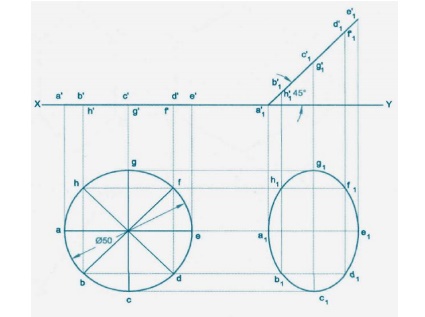
Draw the projections of a circle of
70mm diameter resting on the H.P on a point A of the circumference. The plane
is inclined to the HP such that the top view of it is an ellipse of minor axis
40mm. the top view of the diameter, through the point A is making an angle of
45® with the V.P. determine the inclination of the plane with the HP
8.
The projections of a line measure
80mm in the top view and 70mm in the front view. The midpoint of the line is
45mm in front of VP and 35mm above HP. one end is 10mm in front of VP and
nearer to it. The other end is nearer to HP.Draw the projections of the line.
Find the true length and true inclinations.
9.
Draw the projection of a circle of
70mm diameter resting on the H.P. on a point A of the circumference. The plane
is inclined to the HP such that the top view of it is an ellipse of minor axis
40mm. the top view of the diameter through the point A is making an angle of 45
with the V.P. determine the inclination of the plane with the HP.
10.
A pentagon of side 30mm rests on the
ground on one of its corners with the sides containing the corner being equally
inclined to the ground. The side opposite to the corner on which it rests is
inclined at 30® to the VP and is parallel to the HP. The surface of the
pentagon makes 50® with the ground. Draw the top and front views of the
pentagon.
11.
A line PF, 65mm has its end P, 15mm
above the HP and 15mm in front of the VP. It is inclined at 55®to the VP. Draw
its projections.
Related Topics