Chapter: mechanical : Engineering Graphics
Free Hand Sketching and Perspective Projection
FREE HAND SKETCHING AND PERSPECTIVE PROJECTION
Free Hand sketching of front view, top view and a suitable side view of simple components from their isometric views. Normal perspective of prism, pyramid, cylinder& cone in vertical position by visual ray method only.
Perspective Projection:
The perspective projection, also sometimes called scenographic projection or central projection, is the form of pictorial drawing which most nearly approaches the pictures as seen by the eyes.
Perspective projection is sometimes called scenographic projection or central projection, since the lines of sight converge to a single point or centre. Perspective obtained will depend on the relative position of the object, picture plane and point of sight. In this projection, the eye is assumed to be situated at a definite position relative to the object. The picture plane (vertical plane) is placed between the object and the eye. Visual rays from the eye to the object pierce the picture plane and form an image on it. This image is known as perspective of the object.
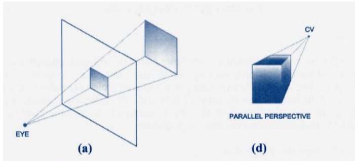
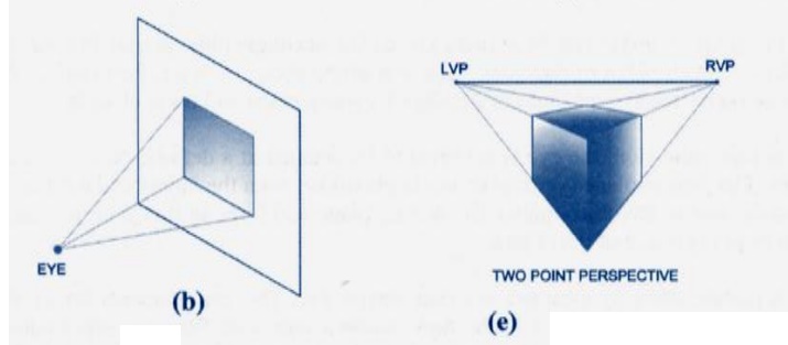
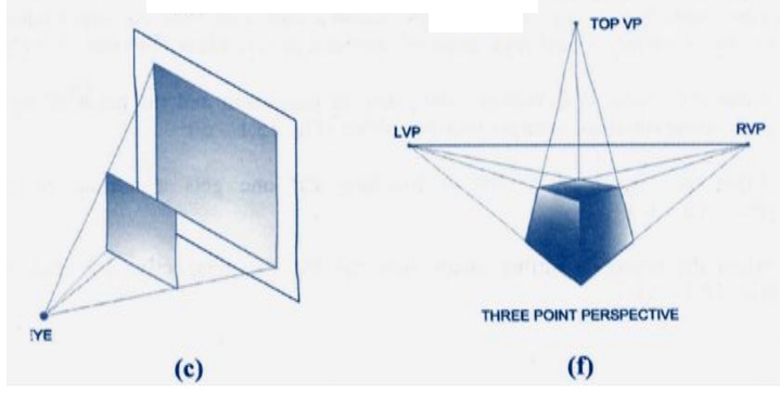
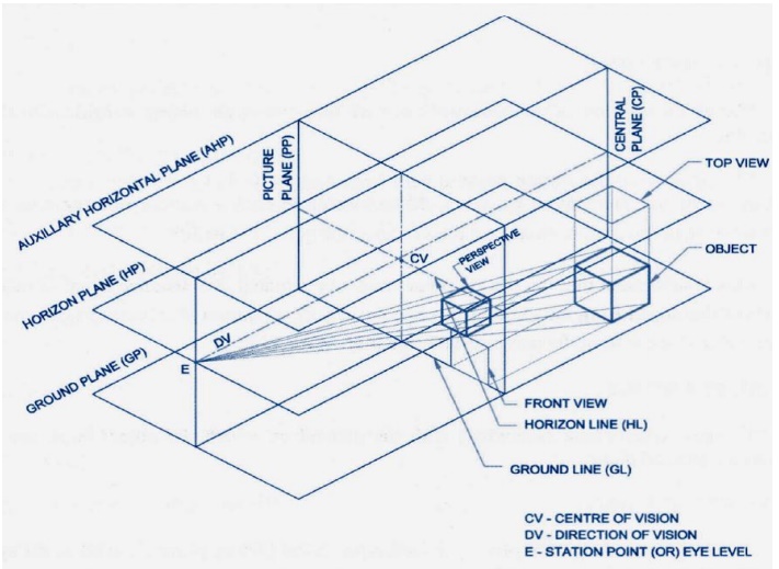
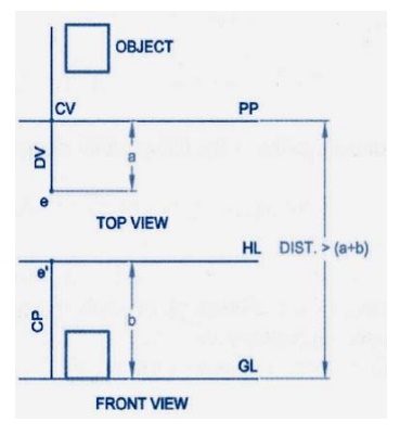
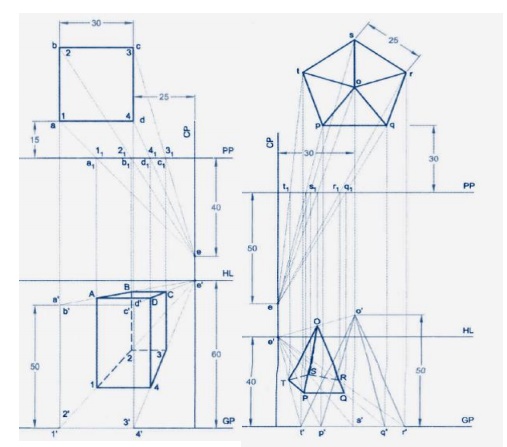
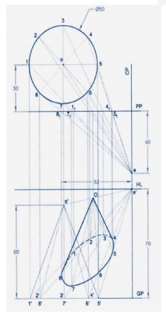
The points at which the visual rays joining the station point and the object pierces the picture plane in both the top and profile views, are projected to intersect each other to give points in the perspective. Since the perspective view is obtained by the intersection of the visual ray, this method is called Visual Ray Method.
IMPORTANCE POINT IN VISUAL RAY METHOD:
1. Draw the PP line to represent the picture plane in the top view
2. Draw the plan of the object based on its position with respect to the PP
3. Draw the Ground Plane, the GP at any convenient distance from PP and project the front view based on the position of object with respect to GP.
4. Locate the position of the central plane with respect to the object and represent it as a line in both the views. On it mark the top view (s) and front view (s') of the station point based on this position with respect to PP and GP.
5. Join all plan points with s and note the intercepts of each line with PP line
6. From each intercept, with PP, draw projector vertically till it meets the line joining the elevation of the corresponding point and s' to get the perspective.
7. Follow the above step to get the perspective of other points of the object
8. Join all these points in proper sequence to get the perspective of the objective
Perspective view of the point P.
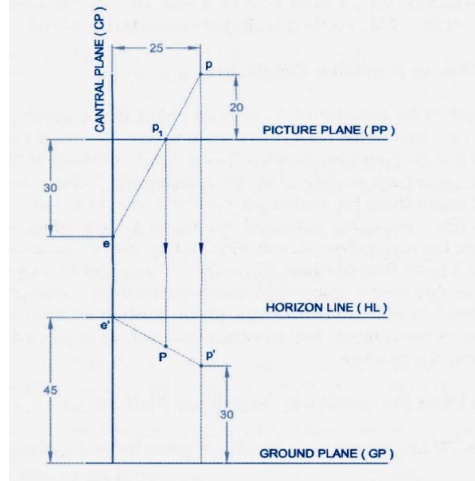
Perspective view of line
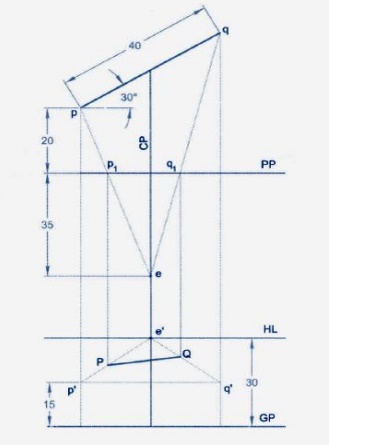
Perspective view of plane
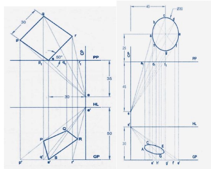
Perspective view of square prism & pyramid
(Resting on the ground on one of its faces /on the ground vertically with an edge of base parallel)
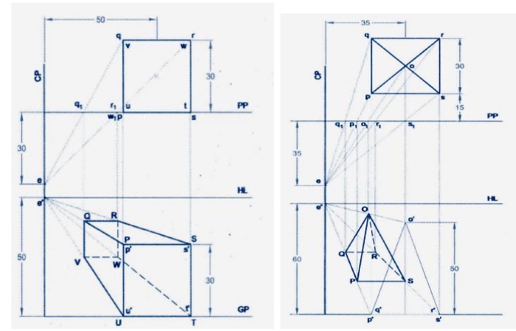
On the ground on its base with a face parallel
Perspective view of CONE
Free Hand Sketching:
In order to achieve a complete shape description, it is necessary to get more than one projection, and therefore, additional planes of projection are used to project more views on them, for the object. As such, the orthographic system of projection is also called multi-view projection method.
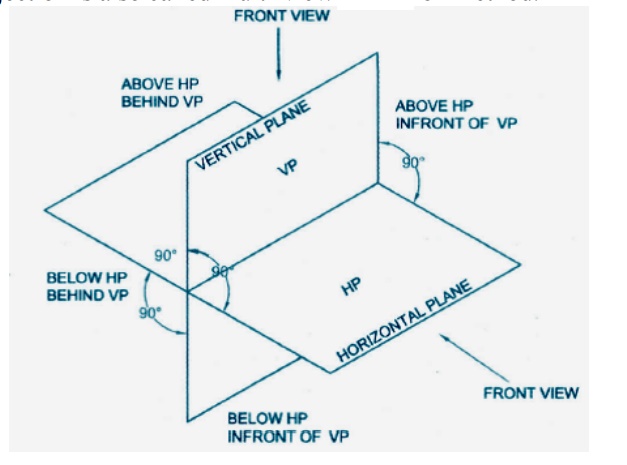
In the orthographic projection drawing, for getting the different views of an object, three main planes are usually used. One of these set up in vertical position is called the vertical plane of projection (VP) or Frontal Plane (FP). The second, set up in horizontal position, i.e., perpendicular to the VP, is called Horizontal Plane (HP). The third, plane set up perpendicular to the vertical and horizontal planes is called Profile Plane (PP).
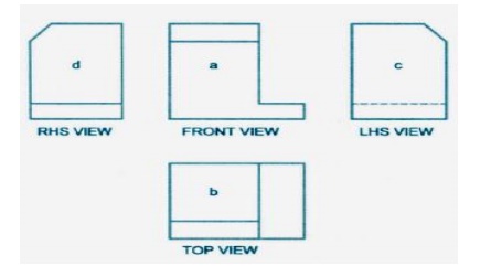
FIRST ANGLE PROJECTION
Symbol of projection

In the first angle projection, the profile view is projected on the opposite side, i.e., Left view is projected on the right plane and vice versa, where as in the third angle projection, it is projected on the same side plane i.e., left view is projected on the left plane.
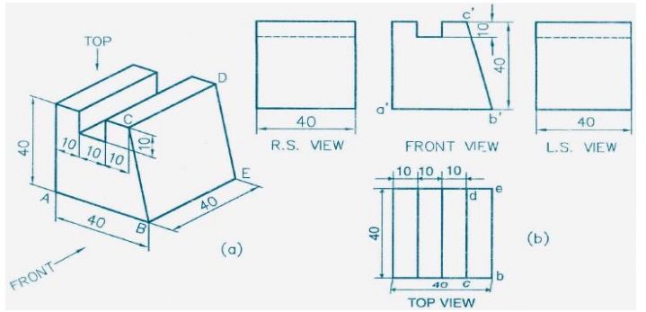
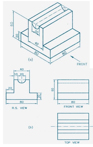
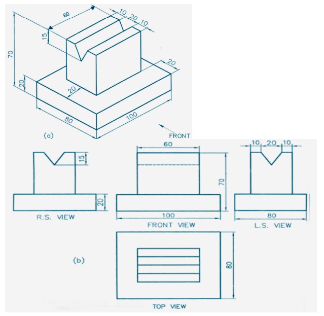
Important Questions
1. A regular hexagonal pyramid of base edge 20mm and height 35mm rests on its base on the ground plane with one of its base edges touching the picture plane. The station point is 30mm above the ground plane and 40mm in front of the pp. the center plane is 30mm to the right of the axis. Draw the perspective projection of the pyramid.
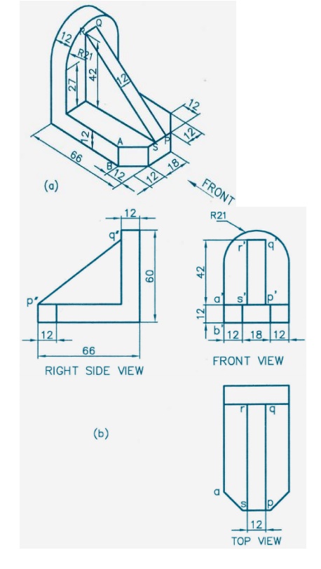
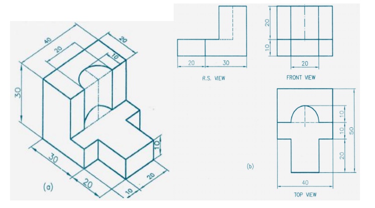
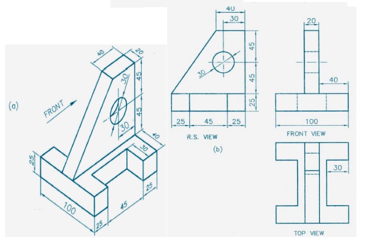
2. Draw by freehand, front view (from X), top view and a suitable side view of the object shown in figure1. Add necessary dimensions of the part.
3. A square prism of 25mm side of base and height 40mm rests with its base on ground such that one of the rectangular faces is inclined at 30®to the picture plane. The nearest vertical edge touches the picture plane. The station point is 50mm in front of the picture plane, 60mm above the ground and lies opposite to the nearest vertical edge the touches the picture plane. Draw the perspective view.
4. Draw the front, top and side views of the isometric view of the object shown in figure 1.
5. Draw the perspective view of a square prism of edge of base 40mm and length 60mm lying on a rectangular face on the ground, with a corner on PP and the bases equally inclined to PP. the station point is 60mm in front of PP and 80mm above GL and lies in a central plane, which is passing through the centre of the prism.
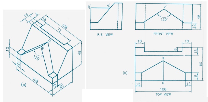
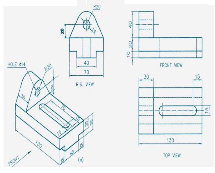
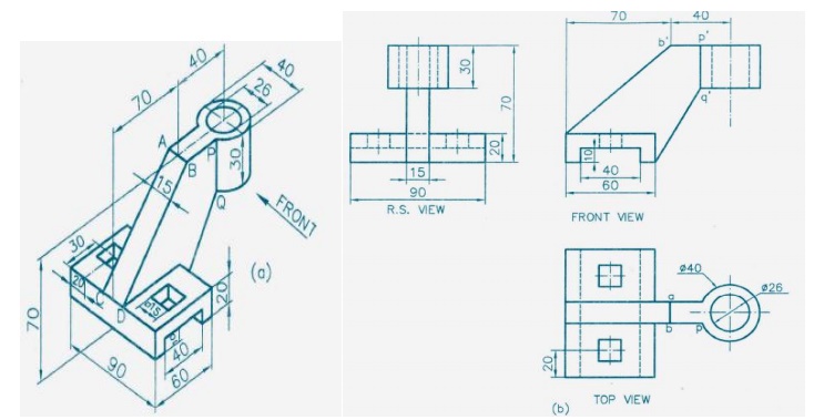
Make free hand sketches of front, top and right side views of the 3D object shown blow
Draw the perspective projection of a cube of 25mm edge, lying on a face on the ground plane, with an edge touching the picture plane and all vertical faces equally inclined to the picture plane. The station point is 50mm in front of the picture plane, 35mm above the ground plane and lies in a center plan which is
10mm to the left of the cube.
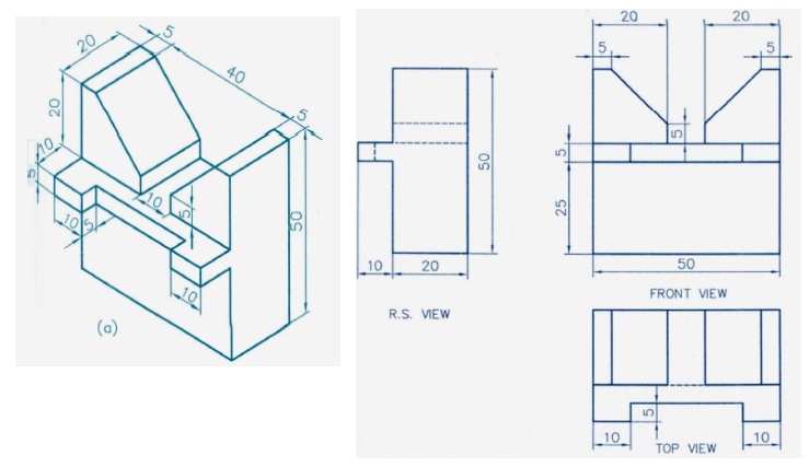
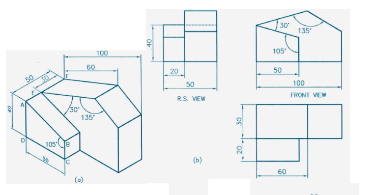
7. Make free hand stretches of the front, top and right side view of the object shown below.
8. Draw the perspective projection of a cub of 25mm edge, lying in a face on the ground plane, with an edge touching the picture plane and all vertical faces equally inclined to the picture plane. The station point is 50mm in front of the picture plane, 35mm above the ground plane and plane and lies in a central plane which is 10mm to the left of the centre of the cube.
9. Draw the front, top, and right side view of the object shown below.
10. A regular hexagonal pyramid of base edge 20mm and height 35mm rests on its base on the ground plane with one of its base edges touching the picture plane. The station point is 30mm above the ground plane and 40mmin front of the PP. the center plane is 30mm to the right of the axis. Draw the perspective projection of the pyramid.
Related Topics