Electricity | Term 2 Unit 2 | 7th Science - Electric circuit and its Types | 7th Science : Term 2 Unit 2 : Electricity
Chapter: 7th Science : Term 2 Unit 2 : Electricity
Electric circuit and its Types
Electric
circuit
It is difficult to draw a realistic diagram of
this circuit. The electrical appliances you use at home have even more
difficult circuits. Can you draw realistic diagrams of such circuits which
contain many bulbs, cells, switches and other components? Do you think it is
easy? It is not easy.
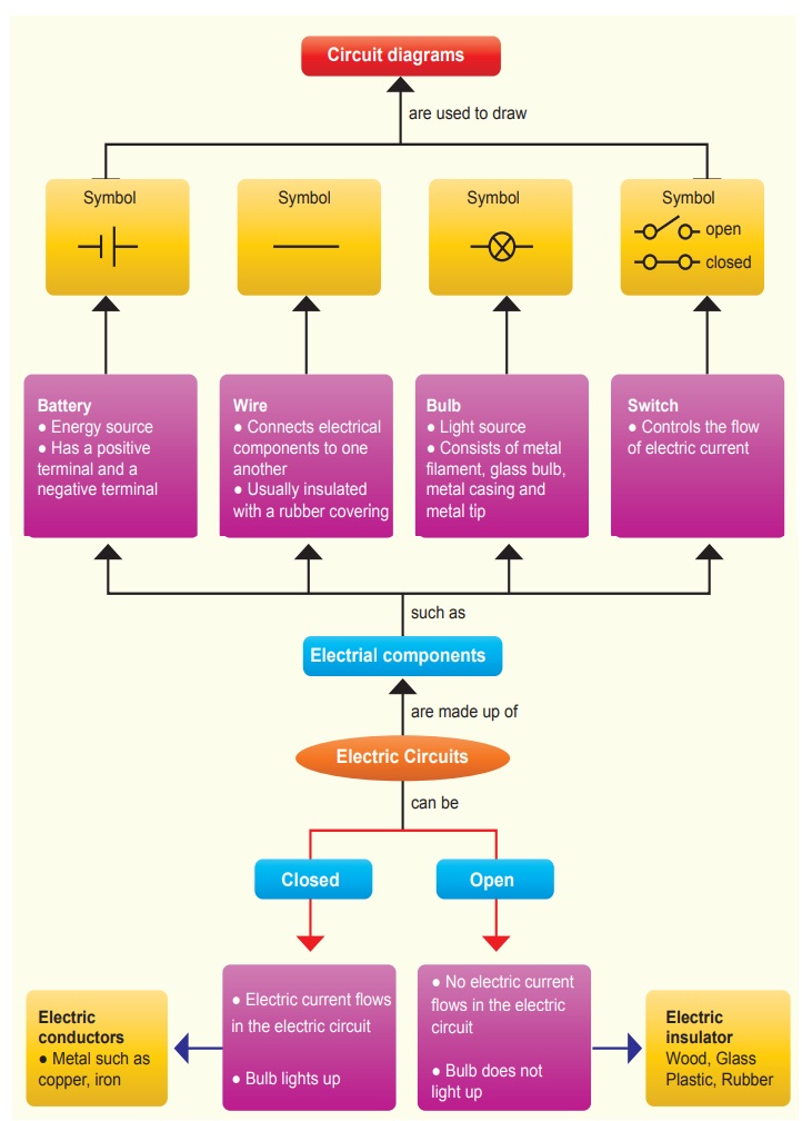
Scientists have tried to make the job easier. They
have adopted simple symbols for different components in a circuit. We can draw
circuit diagrams using these symbols.
Symbols for bulbs, cells and switches are shown in
figure.
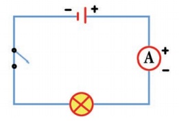
In a cell, the longer line denotes the positive (+) terminal and the short line denotes the negative (-) terminal. We shall use these symbols to show components in the circuits we draw. Such diagrams are called circuit diagrams.
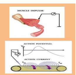
All muscles of our bodies move in
response to electrical impulses
generated naturally in our bodies
Types of
electrical circuits
In the above experiment, we make a circuit with a
bulb and a cell. We make only one kind of the circuit with a cell and a bulb.
But we can make many types of circuits if we have more than one bulb or cells
by connecting these components in different ways .
1. Series
circuit
Two kinds of circuits can be made with two bulbs
and a cell. In this experiment we shall make one of them and study it.
Look at the circuit with two bulbs, and a cell and
a switch given here (Figure)
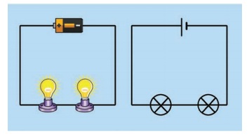
It is clear from the circuit diagram, that the two
bulbs are connected one after the other. The circuit diagram shows the sequence
of the bulbs and cell, not their real position. The way in which the bulbs have
been connected in this circuit is called series connection.
Now make the circuit by joining the two bulbs and
cell. Do both the bulbs light up? Do both glow equally bright? If one glows
less bright, will it shine more brightly if we change its place in the
sequence? Change the sequence of bulbs and notice.
Sometimes bulbs appear to be similar can differ
from each other. So, similar looking bulb do not always glow equally bright
when connected in series. The circuit can be broken at several places. For
example, between the cell and the bulb, between the two bulbs etc.
2. Parallel
Circuit
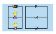
Figure - shows a circuit in which two bulbs are
connected in different places. This is a second type of circuit. Two bulbs in
this circuit are said to be connected in parallel and such circuits are called
parallel circuits.
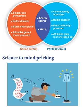
Similarity and
Difference between Series and Parallel Circuit
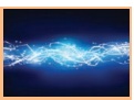
Science to mind pricking
If an electrician attending an electrical fault at
your home gets current shock, will you touch him in order to get rid off him
from current risk? Will you use the wet stick to beat him to avoid further effects
of electric shock?
Why do the electric line man are wear rubber
gloves in their hands while doing electrical works on a electrical pole?
We know that all materials are made up of the
basic building block, the ‘atom’. An atom, in turn, contains electrically
charged particles. Many of these particles are fixed to the atoms but in
conductors (such as all metals) there are lots of particles that are not held
to any particular atom but are free to wander around randomly in the metal.
These are called ‘free charge’.
Short circuit
You might have observed the spark in
the electric pole located nearby your house. Do you know the cause of this
electric spark? This is due to the short circuiting of electricity along its
path. A short circuit is simply a low resistance connection between the two
conductors supplying electrical power to any circuit. Arc welding is a common
example of the practical application of the heating due to a short circuit.

Related Topics