Chapter: Database Management Systems : Introduction to DBMS
ER Model
ER MODEL
Entities:
Entity-a
thing (animate or inanimate) of independent physical or conceptual existence
and distinguishable.
In the University
database context, an individual student, faculty member, a class
room, a courseare entities.
Entity Set or
Entity Type-Collection of entities all having the same properties.
Student
entity
set –collection of all student entities.
Course
entity
set –collection of all course entities.
Attributes:
AttributesEach
entity is described by a set of attributes/properties.studententity
StudName–name
of the student.
RollNumber–the
roll number of the student.
Sex–the
gender of the student etc.
All
entities in an Entity set/type have the same set of attributes.
Cardinality
A business rule indicating the number of times a
particular object or activity may occur.
A collection of tools
for describing:
Data
Data
relationships
Data
semantics
Data
constraints
•
Object-based logical models
– Entity-relationship
model
– Object-oriented
model
– Semantic
model
– Functional
model
•
Record-based logical models
– Relational
model (e.g., SQL/DS, DB2)
– Network
model
– Hierarchical
model (e.g., IMS)
Entity
Relation Model
Perhaps the simplest approach to data
modelling is offered by the Relational Data Model, proposed by Dr. Edgar
F. Codd of IBM in 1970. The model was subsequently expanded and refined by its
creator and very quickly became the main focus of practically all research
activities in databases. The basic relational model specifies a data structure,
the so-called Relation, and several forms of high-level languages to
manipulate relations.
The term relation in this model refers to a
two-dimensional table of data. In other words, according to the model,
information is arranged in columns and rows. The term relation, rather
than matrix, is used here because data values in the table are not necessarily
homogenous (ie. not all of the same type as, for example, in matrices of
integers or real numbers). More specifically, the values in any row are not
homogenous. Values in any given column, however, are all of the
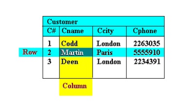
same
type (see Figure ).
Figure
1 A
Relation
A relation has a unique
name and represents a particular entity. Each row of a relation, referred to as
a tuple, is a collection of facts (values) about a particular individual
of that entity. In other words, a tuple represents an instance of the
entity represented by the relation.
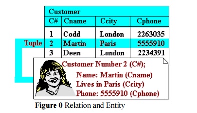
Figure
0 Relation
and Entity
Figure 2 illustrates a
relation calledersonswhoare „Custo customers of some enterprise. Each tuple in
the relation therefore represents a single customer.
The columns of a
relation hold values of attributes that we wish to associate with each entity
instance, and each is labelled with a distinct attribute name at the top of the
column. This name, of course, provides a unique reference to the entire column
or to a particular value of a tuple in the relation. But more than that, it
denotes a domain of values that is defined over all relations in
the database.
The term domain
is used to refer to a set of values of the same kind or type. It should be
clearly understood, however, that while a domain comprises values of a given
type, it is not necessarily the same as that type.
For example, the column „Cname‟ and „Ccity‟ in figure 2 both have values of type string (ie. valid values are any
string). But they denote different domains, ie. „Cname‟ denotes the domain of
customer names while „Ccity‟ denotes the domain of city names. They are
different domains even if they share common values. For example, the string
„Paris‟ can conceivably occur in the Column „Cname‟ (a person named Paris). Its
meaning, however, is quite different to the occurrence of the string „Paris‟ in
the column „Ccity‟ (a city named Paris)!
Thus it is quite
meaningless to compare values from different domains even if they are of the
same type.
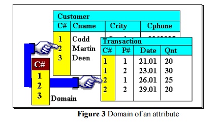
Moreover, in the
relational model, the term domain refers to the current set of values
found under an attribute name. Thus, if the relation in Figure 2 is the only
relation in the database, the domain of „Cname‟ is the set {Codd, Martin,
Deen}, while that of „Ccity‟ is {London, Paris}. But if there were other relations
and an attribute name occurs in more than one of them, then its domain is the union
of values in all columns with that name. This is illustrated in Figure 3 where two
relations each have a column labelled „C domain is defined over all relations,
ie. an attribute name always denotes the same domain in whatever relation in
occurs.
This property of
domains allows us to represent relationships between entities. That is, when
two relations share a domain, identical domain values act as a link
between tuples that contain them (because such values mean the same thing). As
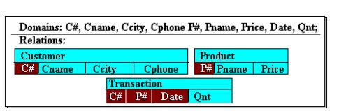
an example, consider a database comprising three relations as shown in Figure .
It highlights a Transaction tuple and a Customer tuple linked through the C#
domain value „2‟, and the same Transactio through the P# domain value „1‟. through
the P# domain value „1‟. The Transaction tuple is a record of a purchase by
customer number „2‟ of product number
„1‟. Through such links, we are able to retrieve the name of the customer and
the product, ie. we are able to state that the customer „Martin‟ bought a
„Camera‟. They help to avoid redundancy in recording data. Without them, the
Transaction relation in Figure will have to include information about the
appropriate Customer and Product in its table. This duplication of data can
lead to integrity problems later, especially when data needs to be modified.
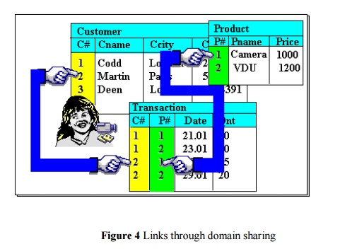
Figure
4 Links
through domain sharing
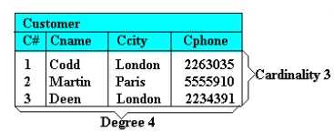
Properties of a Relation
A relation with N columns and M rows (tuples) is
said to be of degree N and cardinality M. This is illustrated in
Figure which shows the Customer relation of degree four and cardinality three. The product of a relation‟s degree and
cardinality is the number of attribute values it contains.
Figure
5 Degree
and Cardinality of a Relation
The
characteristic properties of a relation are as follows:
1.
All entries in a given column are of the
same kind or type
2.
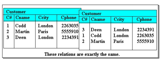
The ordering of columns is immaterial.
This is illustrated in Figure where the two tables shown are identical in every
respect except for the ordering of their columns. In the relational model,
column values (or the value of an attribute of a given tuple) are not
referenced by their position in the table but by name. Thus the display of a
relation in tabular form is free to arrange columns in any order. Of course,
once an order is chosen, it is good practice to use it everytime the relation
(or a tuple from it) is displayed to avoid confusion.
Figure
6 Column
ordering is unimportant
3.
No two tuples are exactly the same. A
relation is a set of tuples. Thus a table that contains duplicate tuples
is not a relation and cannot be stored in a relational database.
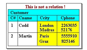
4.
There is only one value for each
attribute of a tuple. Thus a table such as in Figure is not allowed in the
relational model, despite the clear intended representation, ie. that of
customers with two abodes (eg. Codd has one in London and one in Madras). In
situations like this, the multiple values must be split into multiple tuples to
be a valid relation.
Figure
7 A
tuple attribute may only have one value
5. The ordering of
tuples is immaterial. This follows directly from defining a relation as a set
of tuples, rather than a sequence or list. One is free therefore to display a
relation in any convenient way, eg. sorted on some attribute.
The extension of
a relation refers to the current set of tuples in it (see Figure ). This will
of course vary with time as the database changes, ie. as we insert new tuples,
or modify or delete existing ones. Such changes are effected through a DML, or
put another way, a DML operates on the extensions of relations.
The more permanent parts
of a relation,
viz. the relation
name and attribute
names, are
collectively referred
to as its intension or schema. A relation‟s schema eff
constrains) the structure of tuples it is permitted to contain. DML operations
on tuples are
allowed only if they
observe the expressed intensions of the affected relations (this partially
addresses database integrity concerns raised in the last chapter). Any given
database will have a database schema which records the intensions of every
relation in it. Schemas are defined using a DDL.
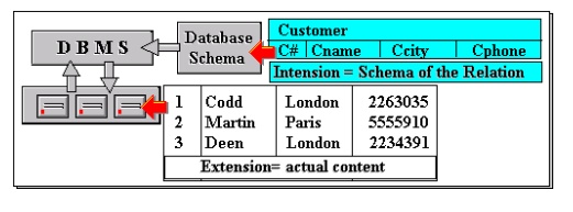
Figure
8 The
Intension and Extension of a Relation
Keys of a Relation
A key is a part of a tuple (one or more
attributes) that uniquely distinguishes it from other tuples in a given
relation. Of course, in the extreme, the entire tuple is the key since each
tuple in the relation is guaranteed to be unique. However, we are interested in
smaller keys if they exist, for a number of practical reasons. First, keys will
typically be used as links, ie. key values will appear in other relations to
represent their associated tuples (as in Figure above). Thus keys should be as
small as possible and comprise only non redundant attributes to avoid
unnecessary duplication of data across relations. Second, keys form the basis
for constructing indexes to speed up retrieval of tuples from a relation. Small
keys will decrease the size of indexes and the time to look up an index.
Consider Figure below. The customer number (C#)
attribute is clearly designed to uniquely identify a customer. Thus we would
not find two or more tuples in the relation having the same customer number and
it can therefore serve as a unique key to tuples in the relation. However,
there may be more than one such key in any relation, and these keys may arise
from natural attributes of the entity represented (rather than a contrived one,
like customer number). Examining again Figure , no two or more tuples have the
same value combination of Ccity and Cphone. If we can safely assume that no
customer will share a residence and phone number with any other customer, then
this combination is one such key. Note that Cphone alone is not - there are two
tuples with the same Cphone value (telephone numbers in different cities that
happen to be the same). And neither is Ccity alone as we may expect many
customers to live in a given city.
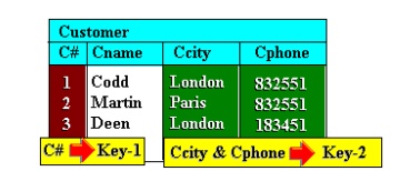
Figure
9 Candidate
Keys
While a relation may have two or more candidate
keys, one must be selected and designated as the primary key in the
database schema. For the example above, C# is the obvious choice as a primary
key for the reasons stated earlier. When the primary key values of one relation
appear in
other relations, they are termed foreign keys.
Note that foreign keys may have duplicate occurrences in a relation, while
primary keys may not. For example, in Figure , the C# in Transaction is a
foreign key and the key value „1‟ occur because a foreign key is only a
reference to a tuple in another relation, unlike a primary key value, which
must uniquely identify a tuple in the relation.
Relational
Schema
A
Relational Database Schema comprises
1.
the definition of all domains
2.
the definition of all relations,
specifying for each
a)
its intension (all attribute names), and
b)
a primary key
Figure 10 shows an example of such a schema which
has all the components mentioned above. The primary keys are designated by
shading the component attribute names. Of course, this is only an informal view
of a schema. Its formal definition must rely on the use of a specific DDL whose
syntax may vary from one DBMS to another.
Figure
10 An
Example Relational Schema
There is, however, a useful notation for relational
schemas commonly adopted to document and communicate database designs free of
any specific DDL. It takes the simple form:
<relation
name>: <list of attribute names>
Additionally,
attributes that are part of the primary key are underlined.
Thus,
for the example in Figure , the schema would be written as follows:
Customer:
( C#, Cname, Ccity, Cphone )
Transaction:
( C#, P#, Date, Qnt )
Product:
( P#, Pname, Price)
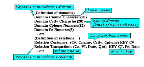
This notation is useful
in clarifying the overall organisation of the database but omits some details,
particularly the properties of domains. As an example of a more complete
definition
using a more concrete DDL, we rewrite some
the schema above
us
The principal components of his notation are
annotated alongside.
Related Topics