Chapter: Linear Integrated Ciruits : Application of Op-Amp
Differentiator
Differentiator:
One of
the simplest of the op-amp circuits that contains capacitor in the
differentiating amplifier.
Differentiator:
As the
name implies, the circuit performs the mathematical operation of
differentiation (i.e) the output waveform is the derivative of the input
waveform. The differentiator may be constructed from a basic inverting
amplifier if an input resistor R1 is replaced by a capacitor C1
.
The
expression for the output voltage can be obtained KCL eqn written at node V2
as follows,
Since the
differentiator performs the reverse of the integrator function.
Thus the
output V0 is equal to RF C1 times the negative
rate of change of the input voltage Vin with time.
The –sign
=> indicates a 1800 phase shift of the output waveform V0
with respect to the input signal.
The below
circuit will not do this because it has some practical problems.
The gain
of the circuit (RF /XC1 )R with R in frequency at a rate of
20dB/decade. This makes the circuit unstable.
Also
input impedance XC1 S with Rin
frequency which makes the circuit very susceptible to high frequency noise.
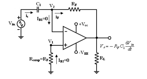
Basic Differetntiator
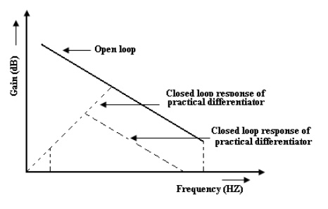
From the
above fig, fa = frequency at which the gain is 0dB and is given by,
Both stability and high frequency noise problems can be corrected by the
addition of 2 components. R1 and CF . This circuit is a
practical differentiator.
From
Frequency f to feedback the gain Rs at
20dB/decade after feedback the gain S at
20dB/decade. This 40dB/ decade change in gain is caused by the R1 C1
and RF CF combinations. The gain limiting frequency fb is
given by,
Where R1
C1 = RF CF
R1
C1 and RF CF =>
helps to reduce the effect of high frequency input, amplifier noise and
offsets.
All R1
C1 and RF CF make the circuit more stable by
preventing the Rin gain
with frequency.
Generally,
the value of Feedback and in turn R1 C1 and RF CF values should be selected
such that
The input
signal will be differentiated properly, if the time period T of the input
signal is larger than or equal to RF C1 (i.e) T > RF
C1
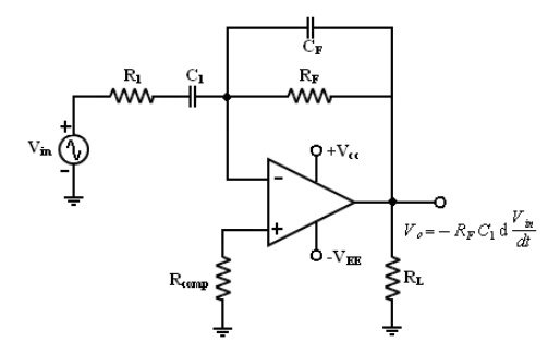
Practical Differentiator
A
workable differentiator can be designed by implementing the following steps.
1. Select fa
equal to the highest frequency of the input signal to be differentiated then
assuming a value of C1< 1μf. Calculate the value of RF
.
2. Choose fb
= 20fa and calculate the values of R1 and CF so that R1
C1 = RFCF .
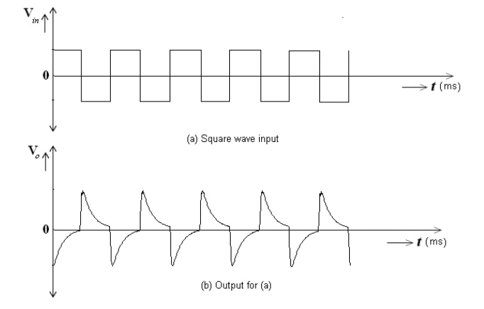
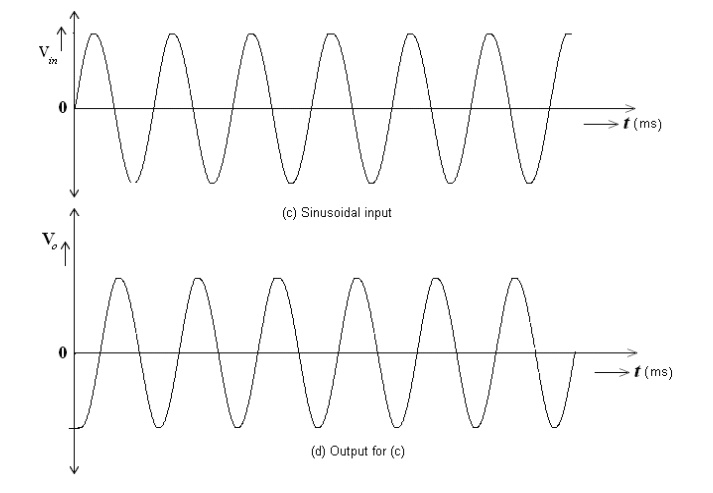
Uses:
Its used
in waveshaping circuits to detect high frequency components in an input signal
and also as a rate of change and detector in FM modulators.
This o/p
for practical differentiator
Related Topics