Chapter: Computer Architecture : Memory and I/O Systems
DMA and Interrupts
DMA AND INTERRUPTS
A special control unit
is provided to allow transfer of a block of data directly between an external
device and the main memory, without continuous intervention by the processor.
This approach is called direct memory access, or DMA.
DMA transfers are
performed by a control circuit that is part of the I/O device interface. We
refer to this circuit as a DMA controller. The DMA controller performs the functions
that would normally be carried out by the processor when accessing the main
memory. For each word transferred, it provides the memory address and all the
bus signals that control data transfer.
Since it has to
transfer blocks of data, the DMA controller must increment the memory address
for successive words and keep track of the number of transfers.
Although a DMA
controller can transfer data without intervention by the processor, its
operation must be under the control of a program executed by the processor. To
initiate the transfer of a block of words, the processor sends the starting
address, the number of words in the block, and the direction of the transfer.
On receiving this information, the DMA controller proceeds to perform the
requested operation. When the entire block has been transferred, the controller
informs the processor by raising an interrupt signal.
While a DMA transfer is
taking place, the program that requested the transfer cannot continue, and the
processor can be used to execute another program. After the DMA transfer is
completed, the processor can return to the program that requested the transfer.
I/O operations are always performed by the operating system of the computer in
response to a request from an application program.
The OS is also
responsible for suspending the execution of one program and starting another.
Thus, for an I/O operation involving DMA, the OS puts the program that
requested the transfer in the Blocked state, initiates the DMA operation, and
starts the execution of another program. When the transfer is completed, the
DMA controller informs the processor by sending an interrupt request. In
response, the OS puts the suspended program in the Runnable state so that it
can be selected by the scheduler to continue execution.

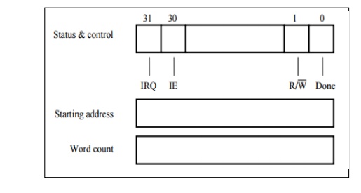
The above figure shows
an example of the DMA controller registers that are accessed by the processor
to initiate transfer operations. Two registers are used for storing the
starting address and the word count. The third register contains status and
control flags. The R/W bit determines the direction of the transfer. When this
bit is set to 1 by a program instruction, the controller performs a read
operation, that is, it transfers data from the memory to the I/O device.
Otherwise, it performs a write operation.
When the controller has
completed transferring a block of data and is ready to receive another command,
it sets the Done flag to 1. Bit 30 is the Interrupt-enable flag, IE. When this flag
is set to 1, it causes the controller to raise an interrupt after it has
completed transferring a block of data. Finally, the controller sets the IRQ
bit to 1 when it has requested an interrupt.
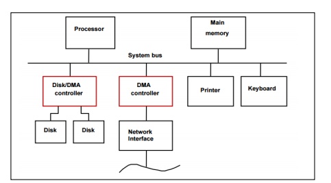
A DMA controller
connects a high-speed network to the computer bus. The disk controller, which
controls two disks, also has DMA capability and provides two DMA channels. It
can perform two independent DMA operations, as if each disk had its own DMA
controller. The registers needed to store the memory address, the word count,
and so on are duplicated, so that one set can be used with each device.
To start a DMA transfer
of a block of data from the main memory to one of the disks, a program writes
the address and word count information into the registers of the corresponding
channel of the disk controller. It also provides the disk controller with
information to identify the data for future retrieval. The DMA controller
proceeds independently to implement the specified operation.
When the DMA transfer
is completed, this fact is recorded in the status and control register of the
DMA channel by setting the Done bit. At the same time, if the IE bit is set,
the controller sends an interrupt request to the processor and sets the IRQ
bit. The status register can also be used to record other information, such as
whether the transfer took place correctly or errors occurred.
Memory accesses by the
processor and the DMA controllers are interwoven. Requests by DMA devices for
using the bus are always given higher priority than processor requests. Among
different DMA devices, top priority is given to high-speed peripherals such as
a disk, a high-speed network interface, or a graphics display device. Since the
processor originates most memory access cycles, the DMA controller can be said
to "steal" memory cycles from the processor. Hence, this interweaving
technique is usually called cycle stealing.
Alternatively, the DMA
controller may be given exclusive access to the main memory to transfer a block
of data without interruption. This is known as block or burst mode. Most DMA
controllers incorporate a data storage buffer. In the case of the network
interface for example, the DMA controller reads a block of data from the main
memory and stores it into its input buffer. This transfer takes place using
burst mode at a speed appropriate to the memory and the computer bus. Then, the
data in the buffer are transmitted over the network at the speed of the
network.

Related Topics