Chapter: Clinical Anesthesiology: Anesthetic Equipment & Monitors : Breathing Systems
Components of Mapleson Circuits
Components
of Mapleson Circuits
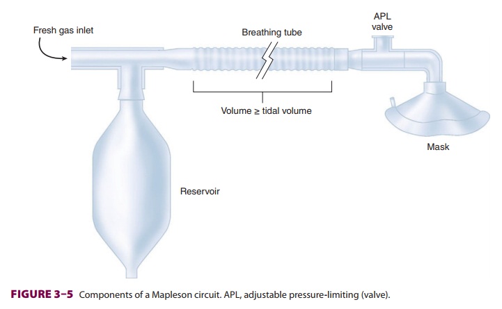
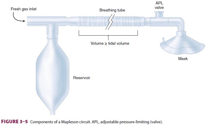
A. Breathing Tubes
Corrugated tubes—made of rubber
(reusable) or plastic (disposable)—connect the components of the Mapleson
circuit to the patient ( Figure 3–5). The large diameter of the tubes
(22 mm) creates a low-resistance pathway and a potential reservoir for anesthetic
gases. To minimize fresh gas flow require-ments, the volume of gas within the
breathing tubes in most Mapleson circuits should be at least as great as the
patient’s tidal volume.
The compliance of the breathing tubes
largely determines the compliance of the circuit. (Compli-ance is defined as
the change of volume produced by a change in pressure.) Long breathing tubes
with high compliance increase the differencebetween the volume of gas delivered
to a circuit by a reservoir bag or ventilator and the volume actually delivered
to the patient. For example, if a breathing circuit with a compliance of 8 mL
gas/cm H2O is pressurized during delivery of a
tidal volume to 20 cm H2O, 160 mL of the tidal volume will be
lost to the circuit. The 160 mL represent a combination of gas compression and
breathing-tube expansion. This is an important consideration in any circuit
deliver-ing positive-pressure ventilation through breathing tubes (eg, circle
systems).
B. Fresh Gas Inlet
Gases (anesthetics mixed with oxygen or
air) from the anesthesia machine continuously enter the circuit through the
fresh gas inlet. As discussed below, the relative position of the fresh gas
inlet is a key differentiating factor in Mapleson circuit performance.
C.
Adjustable Pressure-Limiting Valve (Pressure-Relief Valve, Pop-Off Valve)
As anesthetic gases enter the breathing
circuit, pres-sure will rise if the gas inflow is greater than the combined
uptake of the patient and the circuit. Gases may exit the circuit through an
APL valve, controlling this pressure buildup. Exiting gases enter the operating
room atmosphere or, preferably, a waste-gas scavenging system. All APL valves
allow a variable pressure threshold for venting. The APL valve should be fully
open duringspontaneous ventilation so that circuit pressure remains negligible
throughout inspiration and expi-ration. Assisted and controlled ventilation
require positive pressure during inspiration to expand the lungs. Partial
closure of the APL valve limits gas exit, permitting positive circuit pressures
during reser-voir bag compressions.
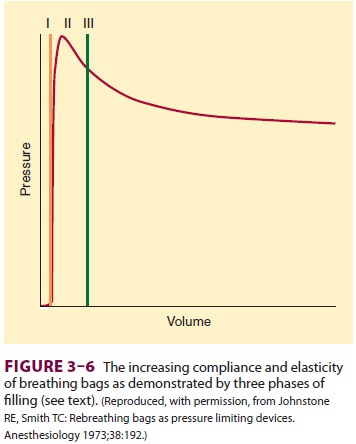
D. Reservoir Bag (Breathing Bag)
Reservoir bags function as a reservoir
of anesthetic gas and a method of generating positive-pressure ventilation.
They are designed to increase in compli-ance as their volume increases. Three
distinct phases of reservoir bag filling are recognizable ( Figure 3–6).
After the nominal 3-L capacity of an adult reservoir bag is achieved (phase I),
pressure rises rapidly to a peak (phase II). Further increases in volume result
in a plateau or even a slight decrease in pressure (phase III). This ceiling
effect provides some mini-mal protection of the patient’s lungs against high
airway pressures, if the APL valve is unintentionally left in the closed
position while fresh gas continues to flow into the circuit.
Related Topics