Chapter: Power Plant Engineering Fundamental
Classification of Power Plant Cycle

CLASSIFICATION OF POWER PLANT CYCLE
Power plants cycle generally divided in to the following groups,
1 Vapour Power Cycle
(Carnot cycle, Rankine cycle, Regenerative cycle, Reheat cycle,
Binary vapour cycle)
2 Gas Power Cycles
(Otto cycle, Diesel cycle, Dual combustion cycle, Gas turbine
cycle.)
1
CARNOT CYCLE
This cycle is of great value to heat
power theory although it has not been possible to construct a practical plant
on this cycle. It has high thermodynamics efficiency.
It is a standard of comparison for all other cycles. The thermal
efficiency (η ) of Carnot cycle is as follows:
η
= (T1 - T2)/T1 where, T1 = Temperature of
heat source
T2 = Temperature of receiver
2
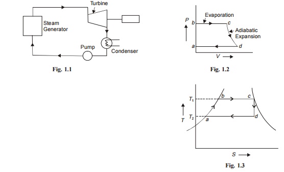
RANKINE CYCLE
Steam engine and steam turbines in which steam is used as
working medium follow Rankine cycle. This cycle can be carried out in four
pieces of equipment joint by pipes for conveying working medium as shown in
Fig. 1.1. The cycle is represented on Pressure Volume P-V and S-T diagram as
shown in Figs. 1.2 and 1.3 respectively.
Efficiency of Rankine cycle
= (H1 - H2)/ (H1 - Hw2)
where, T1
Hl = Total heat of steam at entry
pressure
H2 = Total heat of steam at condenser
pressure (exhaust pressure)
Hw2= Total heat of water at exhaust
pressure
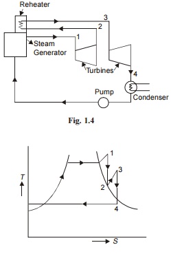
In this cycle steam is extracted from a suitable point in the
turbine and reheated generally to the original temperature by flue gases.
Reheating is generally used when the pressure is high say above 100 kg/cm2.
The various advantages of reheating are as follows:
(i)
It increases dryness fraction of steam at ex-haust so that blade erosion due to
impact of water particles is reduced.
(iii)
It increases the work done per kg of steam and this results in reduced size of
boiler.
The disadvantages of reheating are as follows:
(i)
Cost of plant is increased due to the
reheater and its long connections.
(ii)
It increases condenser capacity due to
in-creased dryness fraction.
If,
H1 = Total heat of steam at 1
H2 = Total heat of steam at 2
H3 = Total heat of steam at 3
H4 = Total heat of steam at 4
Hw4 = Total heat of steam at 4
Efficiency = {(H1 - H2) + (H3 - H4)}/{H1 + (H3 - H2) - Hw4}
4
REGENERATIVE CYCLE (FEED WATER HEATING)
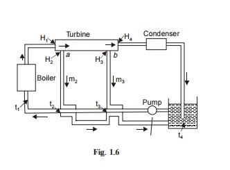
Let,
m2 = Weight of bled steam at a per kg of
feed water heated m2 = Weight of bled steam at a per kg of
feed water heated H1 =
Enthalpies of steam and water in boiler
Hw1
= Enthalpies of steam and water in boiler H2, H3 =
Enthalpies of steam at points a and b
t2,
t3 = Temperatures of
steam at points a and b
H4, Hw4
= Enthalpy of steam and water exhausted to hot well. Work done in turbine per
kg of feed water between entrance and a
= H1 - H2
Work done between a
and b = (1 - m2)(H2 - H3)
Work done between b and
exhaust = (1 - m2 - m3)(H3 - H4)
Total heat supplied per kg of feed water = H1 - Hw2
Efficiency (η ) = Total work done/Total heat supplied
{(H1 - H2) + (1 - m2)(H2 ? H3) + (1 - m2 - m3)(H3 ? H4)}/(H1 ? Hw2)
5
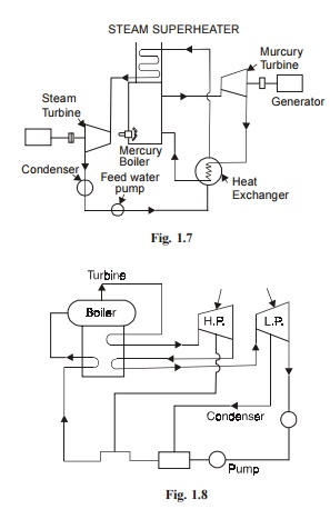
BINARY VAPOUR CYCLE
In this cycle two working fluids are used. Fig. 1.7 shows
Elements of Binary va-pour power plant. The mercury boiler heats the mercury
into mercury vapours in a dry and saturated state.
These mercury vapours expand in the mercury turbine and then
flow through heat exchanger where they transfer the heat to the feed water,
convert it into steam. The steam is passed through the steam super heater where
the steam is super-heated by the hot flue gases. The steam then expands in the
steam turbine.
6
REHEAT-REGENERATIVE CYCLE
In steam power plants using high steam pressure reheat
regenerative cycle is used. The ther-mal efficiency of this cycle is higher
than only re-heat or regenerative cycle. Fig. 1.8 shows the flow diagram of
reheat regenerative cycle. This cycle is commonly used to produce high pressure
steam (90 kg/cm2) to increase the cycle efficiency.
FORMULA
SUMMARY
Rankine efficiency
(H1 - H2)/(H1 - Hw2)
Efficiency ratio or Relative efficiency
Indicated or Brake thermal
efficiency/Rankine efficiency
Thermal efficiency = 3600/m(H1 - Hw2),
m = steam flow/kw hr
Carnot efficiency = (T1 - T2)/T1
Related Topics