Chapter: Advanced Computer Architecture : Memory And I/O
Buses: Connecting I/O Devices to CPU/Memory
Buses : Connecting I/O Devices to
CPU/Memory
Buses
were traditionally classified as CPU-memory buses or I/O buses. I/O buses may
be lengthy, may have many types of devices connected to them, have a wide range
in the data bandwidth of the devices connected to them, and normally follow a
bus standard. CPU-memory buses, on the other hand, are short, generally high
speed, and matched to the memory system to maximize memory-CPU bandwidth.
During the design phase, the designer of a CPU-memory bus knows all the types
of devices that must connect together, while the I/O bus designer must accept
devices varying in latency and bandwidth capabilities. To lower costs, some
computers have a single bus for both memory and I/O devices. In the quest for
higher I/O performance, some buses are a hybrid of the two. For example, PCI is
relatively short, and is used to connect to more traditional I/O buses via
bridges that speak both PCI on one end and the I/O bus protocol on the other.
To indicate its intermediate state, such buses are sometimes called mezzanine
Bus Design Decisions
The
design of a bus presents several options, as Figure 7.8 shows. Like the rest of
the computer system, decisions depend on cost and performance goals. The first
three options in the figure are clear—separate address and data lines, wider
data lines, and multiple-word transfers all give higher performance at more
cost.
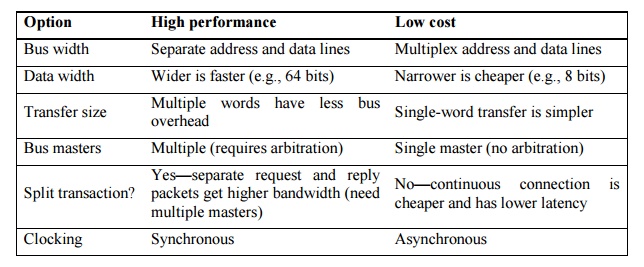
The next
item in the table concerns the number of bus masters. These devices can
initiate a read or write transaction; the CPU, for instance, is always a bus
master. A bus has multiple masters when there are multiple CPUs or when I/O
devices can initiate a bus transaction. With multiple masters, a bus can offer
higher bandwidth by using packets, as opposed to holding the bus for the full
transaction. This technique is called split transactions.
The final
item in Figure 7.8, clocking, concerns whether a bus is synchronous or
asynchronous. If a bus is synchronous, it includes a clock in the control lines
and a fixed protocol for sending address and data relative to the clock. Since
little or no logic is needed to decide what to do next, these buses can be both
fast and inexpensive.
Bus Standards
Standards
that let the computer designer and I/O-device designer work independently play
a large role in buses. As long as both designers meet the requirements, any I/O
device can connect to any computer. The I/O bus standard is the document that
defines how to connect devices to computers.
Ø The Good
Ø Let the
computer and I/O-device designers work independently
Ø Provides
a path for second party (e.g. cheaper) competition
Ø The Bad
Ø Become
major performance anchors
Ø Inhibit
change
Ø How to
create a standard
Ø Bottom-up
Ø Company
tries to get standards committee to approve it’s latest philosophy in hopes
that they’ll get the jump on the others (e.g. S bus, PC-AT bus, ...)
Ø De facto
standards
Ø Top-down
Ø Design by
committee (PCI, SCSI, ...)
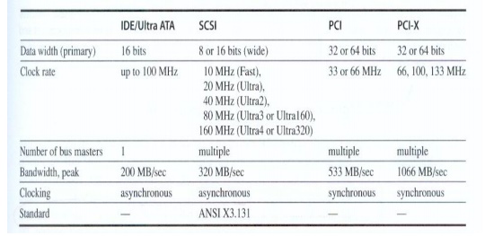
Some
sample bus designs are shown below
Interfacing Storage Devices to the CPU
The I/O
bus is connected to the main memory bus is shown in figure 7.15
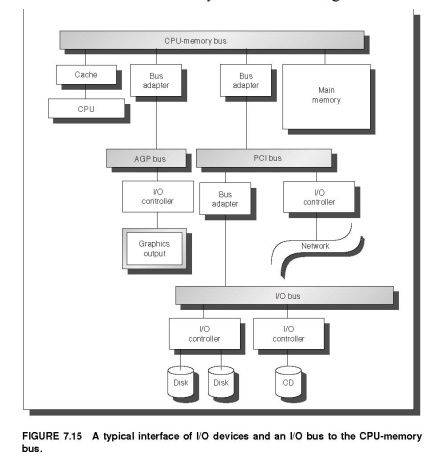
Processor interface with i/o bus can be done with
two techniques one using interrupts and second using memory mapped I/O
Ø I/O
Control Structures
Ø Polling
Ø Interrupts
Ø DMA
Ø I/O
Controllers
Ø I/O
Processors
The
simple interface, in which the CPU periodically checks status bits to see if it
is time for the next I/O operation, is called polling.
Interrupt-driven
I/O, used by most systems for at least some devices, allows the CPU to work on
some other process while waiting for the I/O device. For example, the LP11 has
a mode that allows it to interrupt the CPU whenever the done bit or error bit
is set. In general-purpose applications, interrupt-driven I/O is the key to
multitasking operating systems and good response times.
The
drawback to interrupts is the operating system overhead on each event. In
real-time applications with hundreds of I/O events per second, this overhead
can be intolerable. One hybrid solution for real-time systems is to use a clock
to periodically interrupt the CPU, at which time the CPU polls all I/O devices
The DMA hardware is a specialized processor that transfers data between memory and an I/O device while the CPU goes on with other tasks. Thus, it is external to the CPU and must act as a master on the bus. The CPU first sets up the DMA registers, which contain a memory address and number of bytes to be transferred. More sophisticated DMA devices support scatter/gather, whereby a DMA device can write or read data from a list of separate addresses. Once the DMA transfer is complete, the DMA controller interrupts the CPU. There may be multiple DMA devices in a computer system.
Related Topics