Chapter: Basic Electrical and electronics : Foundamentals of Communication Enginnering
Block diagram of television transmitter
Block diagram of television transmitter
The basic
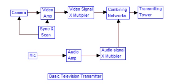
television Broadcast transmitter block diagram is shown in figure (a).
The block
diagram can be broadly divided into two separate section, viz., one that -
Generates an electronic signal (called video signal) corresponding to the
actual picture and then uses this video signal to modulate an R-F carrier so as
to be applied to the transmitting antenna for transmission, other that generates
an electronic signal (called audio signal) containing sound information and
then uses this signal to modulate another RF carrier and then applied to the
transmitting antenna for transmission.
However
only one antenna is used for transmission of the video as well as audio
signals. Thus these modulated signals have to be combined together in some
appropriate network. In addition there are other accessories also. For
instance, video as well as audio signals have to be amplified to the desired
degree before they modulate their respective RF carriers.
This
function is performed by video and audio amplifiers. The block picture signal
transmitter and audio signal transmitter shown in figure (a) may consist of
modulators as the essential component; Video signal transmitter employs an AM
transmitter as amplitude-modulation is used for video signals whereas audio
signal transmitter employs FM modulator as frequency modulation is used for
sound information. Scanning circuits are used to mike the electron beam scan
the actual picture to produce the corresponding video signal. The scanning by
electron beam is in the receiver too. The beam scans the picture tube to
reproduce the original picture from the video signal and this scanning at the
receiver must be matched properly to the scanning at the transmitter. It is for
this reason that synchronizing Circuits are used at the transmitter as well as
receiver.
Complete TV
transmitter Block Diagram
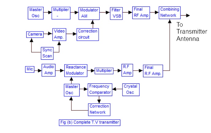
Figure
(b) depicts the complete block diagram of a Television Broadcast Transmitter.
The important block have already been discussed individually in the preceding
sections. that makes understanding of the diagram shown here much more simple.
A brief explanation is given ahead. The block diagram can be broadly divided
into two -sections, viz., an amplitude modulated transmitter and a frequency
modulated transmitter. Former is used for video modulation whereas latter is
used for audio modulation.
Master
oscillator in both generates an RF carrier frequency. Generally, a master
oscillator generates a sub multiple of carrier and then drives harmonic
generators (frequency multipliers) to achieve correct value carrier. Harmonic
generators are nothing but class C tuned amplifiers whose output tuned circuit
is to tuned to some harmonic of the input signal. In actual practice, master
oscillator and harmonic generator are s crated or isolated by a buffer stage to
av214Joactrrig of the harmonic generator on the oscillator output. The carrier
is then fed to an amplitude modulator in video transmitter and a frequency
modulator in audio transmitter. Into-the modulator, the modulation signal is
also fed with proper amplitude. Since low-level modulation is employed, the
modulating signal is amplified by linear amplifiers up-to the desired degree
required for transmission. Video and audio signals on separate carriers are
then combined together so as to be fed to the transmitting antenna as on
signal.
Block diagram of television receiver
Television Receiver
A radio
receiver designed to amplify and convert the video and audio radio- frequency
signals of a television broadcast that have been picked up by a television
antenna; the receiver reproduces the visual image broadcast and the
accompanying sound. Television receivers are designed for color or black-and-
white operation; both non portable and portable models are produced. Those
manufactured in the USSR are capable of receiving signals from television
stations transmitting in specifically assigned portions of thevery-high-frequency
(VHF) band (48.5–100 megahertz and 174– 230 megahertz; 12 channels) and ultra
high-frequency (UHF) band (470– 638 megahertz; several tens of channels).
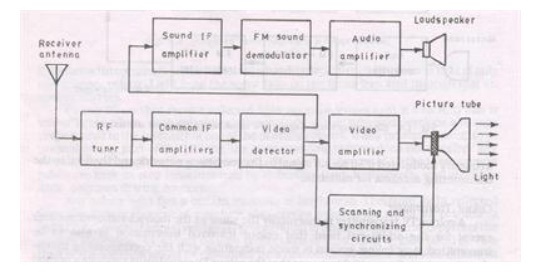
Television
receivers must simultaneously amplify and convert video and audio radio-
frequency signals. They are usually designed with a super heterodyne circuit,
and versions differ in the methods used to extract and amplify the audio
signal. The principal components of a television receiver are shown in Figure1.
The tuner
selects the signals of the desired channel and converts them to a lower
frequency within the inter mediate-frequency pass band. The signal-processing
circuits include an intermediate-frequency amplifier for the video signal, an
amplitude detector, a video amplifier for the brightness signal, and, incolor
receivers, a color- processing circuit for the chrominance signal. The
processing circuit produces a brightness signal and a color- difference signal,
which are fed to the control electrodes of a kinescope; an audio signal, which
is fed to the audio channel; and horizontal and vertical synchronizing pulses
(or a composite television signal), which are fed to a scanning generator. In
the color television system used in the USSR , the color-processing circuit for
the chrominance signal consists of a band- pass amplifier, in which the
chrominance signal is extracted, channels for the direct and delayed signals,
an electronic switching device, two frequency detectors for the color-
difference signals, a matrix circuit, and amplifiers for the three
color-difference signals. The color processing circuit has provisions for the
extraction and decoding of the chrominance signal and for line selection, as
well as chrominance disconnect circuits that operate when black-and-white transmissions
are received.
The
scanning generators include horizontal and vertical scanning circuits that
produce sawtooth c urrentsin the horizontal and vertical scanning coils of the
deflection system.
The high
voltage for feeding the second anode of the kinescope is derived from a special
high voltage winding of the line transformer or by rectifying pulses from the
transformer; the volt age for the focusing electrode is similarly derived.
The
kinescope’s interface includes static and dynamic white balance controls,
switches for exting uishingthe electron guns, and regulators for focusing the
beams. The demagnetizing circuit for a color kinescopecreates a damped
alternating current in a demagnetizing loop that circles the kine scope screen.
The current demagnetizes the shadow mask and tube rim, which are made of steel.
The audio section consists of an amplifier for the difference frequency, which
in the USSR is 6.5 megahertz, a frequency detector for the audio signal, and a
low-frequency amplifier from which the audio signal is fed to a high- quality
acoustical system, usually composed of several loudspeakers. The power- supply
section converts mains voltage into the supply voltages for all components of
the television set, including the kinescope and vacuum tube heaters.
Related Topics