Chapter: Physics : Properties of Mater and Thermal Physics
Bending of Beams
BENDING
OF BEAMS
1
Beams: A beam is defined as a rod or bar.
Circular or rectangular of uniform cross section whose length is very much
greater than its other dimensions, such as breadth and thickness. It is
commonly used in the construction of bridges to support roofs of the buildings
etc. Since the length of the beam is much greater than its other dimensions the
shearing stresses are very small.
Assumptions:
While studying about
the bending of beams, the following assumptions have to be made.
1.
The length of the beam
should be large compared to other dimensions.
2.
The load(forces)
applied should be large compared to the weight of the beam
3.
The cross section of
the beam remains constant and hence the geometrical moment of inertia ig
also remains constant
4.
The shearing stresses
are negligible
5.
The curvature of the
beam is very small
2
Bending of a Beam and neutral axis
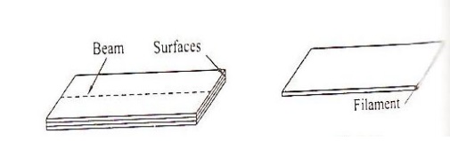
Let us consider a beam of
uniform rectangular cross section in the figure. A beam may be assumed to
consist of a number of parallel
longitudinal metallic fibers placed one over the other and are called as
filaments as shown in the figure.
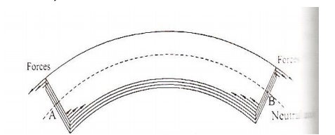
Let the beam be subjected to
deforming forces as its end as shown in the figure. Due to the deforming force
the beam bends. We know the beam consist of many filaments. Let us consider a
filament AB at the beam. It is found that the filaments(layers) lying above AB
gets elongated, while the filaments lying below AB gets compressed. Therefore
the filaments i.e layer AB which remains unaltered is taken ass the reference
axis called neutral axis and the plane is called neutral plane. Further, the
deformation of any filaments can be measured with reference to the neutral
axis.
3 EXPRESSION FOR BENDING MOMENT
Let
us consider a beam under the action of deforming forces. The beam bends into a
circular arc as shown in the figure. Let AB be the neutral axis of the beam.
Here the filaments above AB are elongated and the filaments below AB are
compressed. The filament AB remains unchanged.
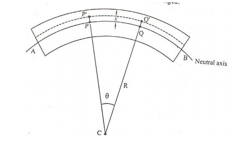
Let
PQ be the chosen from the neutral axis. If R is the radius of curvature of the
neutral axis and ᶿ is the angle subtended by it at its center of curvature’C’
Then
we can write original length
PQ=Rᶿ ………………………………………………………. 1
Let
us consider a filament P’Q’ at a distance ‘X’ from the neutral axis.
We
can write extended length
P’Q’=(R+x)ᶿ ………………………………………………2
From
equations 1 and 2 we have,
Increase
in length=P’Q’-PQ
On
increase in its length=(R=x)θ-Rθ
Increase
in length=xθ …………………………………….3
We
know linear strain=increase in length\original length
Linear
strain=xθ\Rθ=x\R ………………………………4
We
know, the youngs modulus of the material
Y=stress\linear
strain
Or
stress=y*linear strain …………………….5
Substituting
4 in 5, we have
Stress=Yx\R
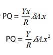
If
δA is the area of cross section of the filament P’Q’, then,
The
tensile force on the area δA=stress*Area
Ie.
Tensile force=(Yx\R )
We
know the memont of force= force*Perpendicular distance
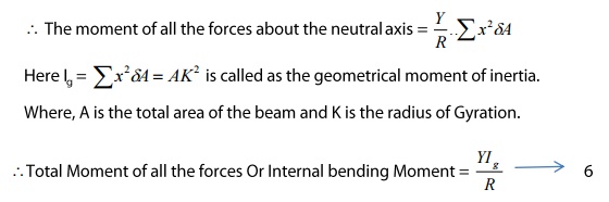
Moment of the tensile force about the neutral axis AB
or
The
moment of force acting on both the upper and lower halves of the neutral axis
can be got by summing all the moments of tensile and compressive forces about
the neutral axis
SPECIAL CASES
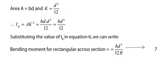
a)
Rectangular
Cross section
If ‘b’ is the breadth
and ‘d’ is the thickness of the beam, them
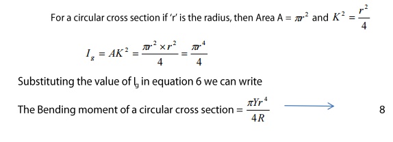
b)
Circular
Cross Section
4 NON-UNIFORM
BENDING-DEPRESSION OF THE MID POINT OF A BEAM LAODED AT THE MIDDLE THEORY
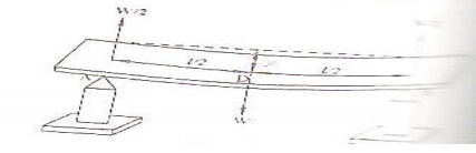
Let us consider a beam of length
‘l’ (distance between the two knife edges) supported on the two knife edges A
and B as shown in the figure. The load of weight ‘W’ is suspended at the centre
‘C’. It is found that the beam bends and the maximum displacement is at the
point ‘D’Where the load is given.
Due to the load (W) applied, at the
middle of the beam the reaction W/2 is acted vertically upwards at each knife
edges. The bending is celled Non-Uniform bending
The beam may be
considered as two cantilevers, whose free end carries a load of W/2 and fixed
at the point ‘D’.
Hence we can say the
elevation of A above D as the depression below ‘A’. We know the depression of a
cantilever
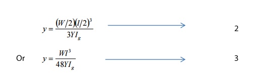
Therefore substituting
the value l and l/2 and was W/2 in the expression for the depression of the
cantilever we have
5 UNIFORM
BENDING-ELEVATION AT THE CENTER OF THE BEAM LOADED AT BOTH THE ENDS THEORY:
Let us consider a beam of
negligible mass, supported symmetrically on the two knife edges A and B as
shown. Let the length between A and B is’l’. Let equal weights W; be added to
either end of the beam C and D.
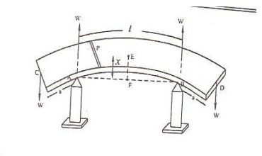
Let CA=BD
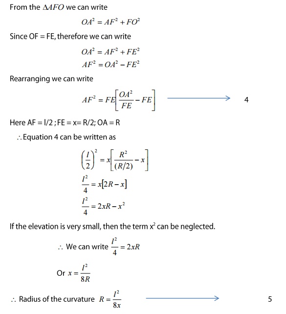
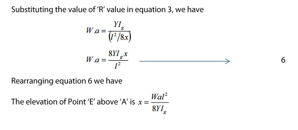
Due to load applied the
beam bends from position F and e into an arc of a circle and produces as
elevation ‘x’ from position F and E. Let ‘W’ be the reaction produced at the
points A and B acts vertically upwards as shown in figure.
Consider a point ‘P’ on
the cross section of the beam. Then the forces acting on the part PC of the
beam are
a)
Force W at ‘C’ and
b)
Reaction W at A as
shown in the figure
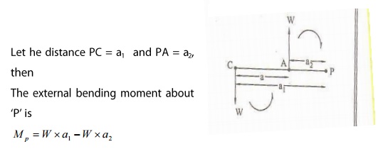
Here the clockwise
moment is taken as negative and anticlockwise moment is taken as positive.
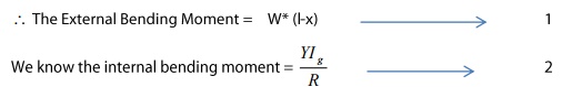
External bending moment
about P can be written as
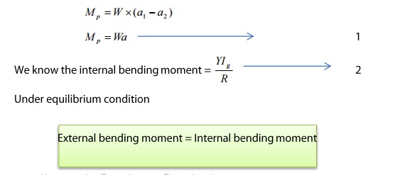
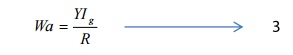
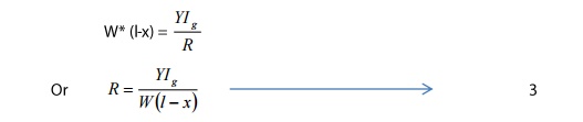
External bending moment
= Internal bending moment
We can write Equation 1
= Equation 2
Since
for a given load (W) Y, Ig and R are constant the bending is called Bending.
Here it is found that the elevation ‘x’ forms an arc of the circle of radius
‘R’, as shown in the figure.
6 DEPRESSION OF A
CANTILEVER WHEN LOADED AT ITS END CANTILEVER:
A
cantilever is a beam fixed horizontally at one end loaded to the other end.
THEORY:
Let
us consider a beam fixed at one end and loaded at its other end as shown in the
figure.
Due
to load applied at the free end, a couple is created between the two forces
a.
Force (load ‘W’) applied at the free end towards downward direction and
b.
Reaction(R) acting in the upward direction at the supporting end
The
external bending couple tends to bend in the clockwise direction. But since one
end of the beam is fixed, the beam cannot rotate. Therefore external bending
couple must be balanced by another equal and opposite couple, created due to
elastic nature of the body
i.e.
called as internal beading moment.
Under
equilibrium condition
External
bending moment = Internal bending Moment
7 DEPRESSION OF A
CANTILEVER – LOADED AT ITS ENDS
THEORY:
LET
‘I’ be the length of the cantilever OA fixed at ‘O’. Let ‘W’ be the weight
suspended (loaded) at the free end of the cantilever. Due to the load applied
the cantilever moves to a new position OA’ as shown in this figure.
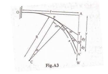
Let
us consider an element PQ of the beam of length dx, at a distance OP=x from the
fixed end. Let ‘C’ be the center of curvature of the element PQ and let ‘R’ be
the radius of the curvature.
Due
to the load applied at the free end of the Cantilever, an external couple
(Distance between the two equal and opposite forces) is (l-x).
We
know under thermal equilibrium
External
bending moment = Internal bending Moment
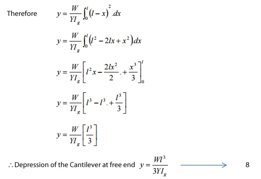
Therefore,
we can write Eqn 1 = Eqn 2
Two
tangents are drawn at points P and Q, which meet the vertical line AA’ at T and
S respectively
Let
the smallest depression produced from T to S = dy and
Let
the angle between the two tangents = dƟ
Then
we can write
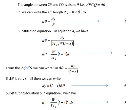
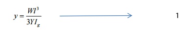
Total
depression at the end of the cantilever can be derived by integrating the
equation 7 within the limits ‘0’ to ‘1’.
SPECIAL
CASES:
a.
RECTANGULAR CROSS SECTION
If
‘b’ is the breadth and ‘d’ is the thickness of the beam then we know
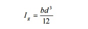
Substituting
the value of Ig in equation 8 we can write
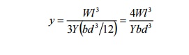
The
depression produced at the free end for a rectangular cross section
b.
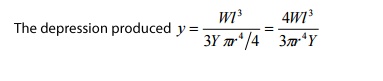
CIRCULAR CROSS SECTION
If
‘r’ is the radius of the circular cross section, then

Substituting
the value of Ig in equation 8 we can write
Related Topics