Chapter: Linear Integrated Ciruits : Application of Op-Amp
Voltage follower
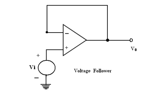
Voltage follower:
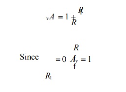
If R1=∞
and Rf=0 in the non inverting amplifier configuration .The amplifier act as a
unity-gain amplifier or voltage follower.
That is
The
circuit consist of an op-amp and a wire connecting the output voltage to the
input ,i.e the output voltage is equal to the input voltage, both in magnitude
and phase.V0=Vi
Since the
output voltage of the circuit follows the input voltage, the circuit is called
voltage follower. It offers very high input impedance of the order of MΩ and
very low output impedance.
Therefore,
this circuit draws negligible current from the source. Thus, the voltage
follower can be used as a buffer between a high impedance source and a low
impedance load for impedance matching applications.
1. Voltage to Current Converter
with floating loads (V/I):
1.
Voltage to current converter in which load resistor
RL is floating (not connected to ground).
2.
Vin is applied to the non inverting input terminal,
and the feedback voltage across R1 devices the inverting input terminal.
3.
This circuit is also called as a current – series
negative feedback amplifier.
4. Because
the feedback voltage across R1 (applied Non-inverting terminal) depends on the
output current i0 and is in series with the input difference voltage Vid
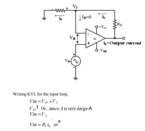
From the
fig input voltage Vin is converted into output current of Vin/R1 [Vin ->i0 ]
. In other words, input volt appears across R1. If R1 is a precision resistor,
the output current (i0 = Vin/R1 ) will be precisely fixed.
Applications:
1.
Low voltage ac and dc voltmeters
2.
Diode match finders
3.
LED
4.
Zener diode testers.
2. Voltage – to current converter
with Grounded load:
This is
the other type V – I converter, in which one terminal of the load is connected to
ground.
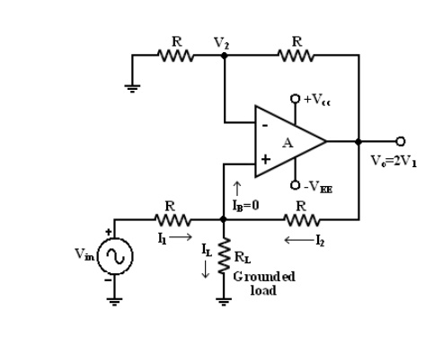
Analysis of the circuit:
The
analysis of the circuit can be done by following 2 steps.
1.
To determine the voltage V1 at the non-inverting
(+) terminals and
2.
To establish relationship between V1 and the load
current IL .
Applying
KCL at node V1 we can write that,
Related Topics