Chapter: Mechanical : Manufacturing Technology : Theory Of Metal Cutting
Single-point cutting tool
Single-point cutting tool
As distinguished from other cutting tools such as a The cutting edge is ground to suit a particular machining operation and may be re sharpened or reshaped as needed. The ground tool bit is held rigidly by a tool holder while it is cutting.
Back Rake is to help control the direction of the chip, which naturally curves into the work due to the difference in length from the outer and inner parts of the cut. It also helps counteract the pressure against the tool from the work by pulling the tool into the work.
Side Rake along with back rake controls the chip flow and partly counteracts the resistance of the work to the movement of the cutter and can be optimized to suit the particular material being cut. Brass for example requires a back and side rake of 0 degrees while aluminum uses a back rake of 35 degrees and a side rake of 15 degrees. Nose Radius makes the finish of the cut smoother as it can overlap the previous cut and eliminate the peaks and valleys that a pointed tool produces. Having a radius also strengthens the tip, a sharp point being quite fragile.
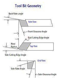
All the other angles are for clearance in order that no part of the tool besides the actual cutting edge can touch the work. The front clearance angle is usually 8 degrees while the side clearance angle is 10-15 degrees and partly depends on the rate of feed expected.
Minimum angles which do the job required are advisable because the tool gets weaker as the edge gets keener due to the lessening support behind the edge and the reduced ability to absorb heat generated by cutting.
The Rake angles on the top of the tool need not be precise in order to cut but to cut efficiently there will be an optimum angle for back and side rake.
Forces in machining
If you make a free body analysis of the chip, forces acting on the chip would be as follows.
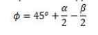
At cutting tool side due to motion of chip against tool there will be a frictional force and a normal force to support that. At material side thickness of the metal increases while it flows from uncut to cut portion. This thickness increase is due to inter planar slip between different metal layers. There should be a shear force (Fs) to support this phenomenon. According to shear plane theory this metal layer slip happens at single plane called shear plane. So shear force acts on shear plane. Angle of shear plane can approximately determined using shear plane theory analysis. It is as follows
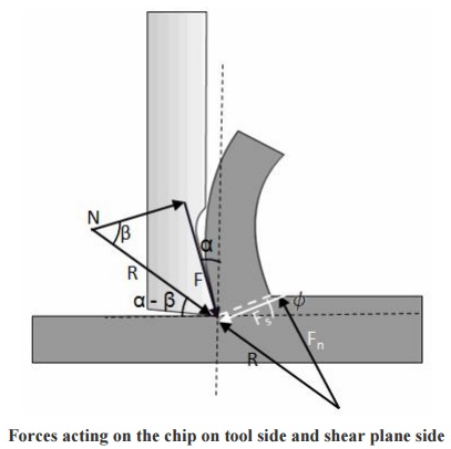
Forces acting on the chip on tool side and shear plane side
Shear force on shear plane can be determined using shear strain rate and properties of material. A normal force (Fn) is also present perpendicular to shear plane. The resultant force
(R) at cutting tool side and metal side should balance each other in order to make the chip in equilibrium. Direction of resultant force, R is determined as shown in Figure.
Related Topics