Chapter: Fundamentals of Database Systems : File Structures, Indexing, and Hashing : Disk Storage, Basic File Structures, and Hashing
Secondary Storage Devices
Secondary Storage Devices
In this section we describe some characteristics of magnetic disk and
magnetic tape storage devices. Readers who have already studied these devices
may simply browse through this section.
1. Hardware Description
of Disk Devices
Magnetic disks are used for storing large amounts of data. The most
basic unit of data on the disk is a single bit
of information. By magnetizing an area on disk in certain ways, one can make
it represent a bit value of either 0 (zero) or 1 (one). To code information,
bits are grouped into bytes (or characters). Byte sizes are typically 4
to 8 bits, depending on the computer and the device. We assume that one
character is stored in a single byte, and we use the terms byte and character
interchangeably. The capacity of a
disk is the number of bytes it can store, which is usually very large. Small floppy disks used with
microcomputers typically hold from 400 KB to 1.5 MB; they are rapidly going out
of circulation. Hard disks for personal computers typically hold from several
hundred MB up to tens of GB; and large disk packs used with servers and
mainframes have capacities of hundreds of GB. Disk capacities continue to grow
as technology improves.
Whatever their capacity, all disks are made of magnetic material shaped
as a thin circular disk, as shown in Figure 17.1(a), and protected by a plastic
or acrylic cover.
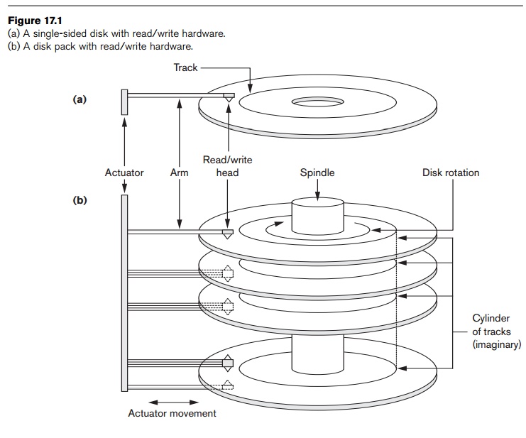
A disk is single-sided if it
stores information on one of its surfaces only and double-sided if both surfaces are used. To increase storage
capacity, disks are assembled into a
disk pack, as shown in Figure
17.1(b), which may include many disks and there-fore many surfaces. Information
is stored on a disk surface in concentric circles of small width, each having a distinct diameter. Each circle is called a track.
In disk packs, tracks with the same
diameter on the various surfaces are called a cylinder because of the shape they would form if connected in
space. The concept of a cylinder is important because data stored on one
cylinder can be retrieved much faster than if it were distributed among
different cylinders.
The number of tracks on a disk ranges from a few hundred to a few
thousand, and the capacity of each track typically ranges from tens of Kbytes
to 150 Kbytes. Because a track usually contains a large amount of information,
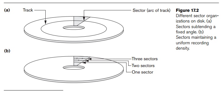
it is divided into smaller blocks or sectors. The division of a track into sectors is hard-coded on the disk
surface and cannot be changed. One type of sector organization, as shown in
Figure 17.2(a), calls a portion of a track that subtends a fixed angle at the
center a sector. Several other sector organizations are possible, one of which
is to have the sectors subtend smaller angles at the center as one moves away,
thus maintaining a uniform density of recording, as shown in Figure 17.2(b). A
technique called ZBR (Zone Bit Recording) allows a range of cylinders to have the
same number of sectors per arc. For example, cylinders 0–99 may have one sector
per track, 100–199 may have two per track, and so on. Not all disks have their
tracks divided into sectors.
The division of a track into equal-sized disk blocks (or pages) is
set by the operating system during disk formatting
(or initialization). Block size is
fixed during initialization and cannot be changed dynamically. Typical disk
block sizes range from 512 to 8192 bytes. A disk with hard-coded sectors often
has the sectors subdivided into blocks during initialization. Blocks are
separated by fixed-size interblock gaps,
which include specially coded control information written during disk
initialization. This information is used to determine which block on the track
follows each
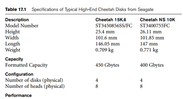
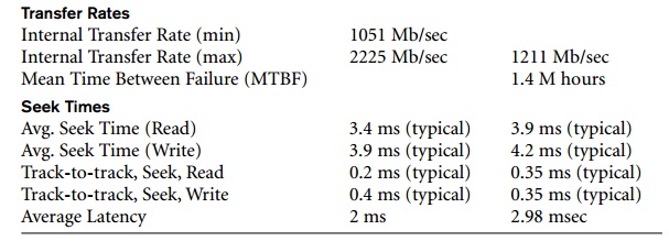
interblock gap. Table 17.1 illustrates the specifications of typical
disks used on large servers in industry. The 10K and 15K prefixes on disk names
refer to the rotational speeds in rpm (revolutions per minute).
There is continuous improvement in the storage capacity and transfer
rates associated with disks; they are also progressively getting
cheaper—currently costing only a fraction of a dollar per megabyte of disk
storage. Costs are going down so rapidly that costs as low 0.025 cent/MB—which
translates to $0.25/GB and $250/TB—are already here.
A disk is a random access
addressable device. Transfer of data between main memory and disk takes place
in units of disk blocks. The hardware
address of a block—a combination of a cylinder number, track number
(surface number within the cylinder on which the track is located), and block
number (within the track) is supplied to the disk I/O (input/output) hardware.
In many modern disk drives, a single number called LBA (Logical Block
Address), which is a number between 0 and n
(assuming the total capacity of the disk is n + 1 blocks), is mapped automatically to the right block by the
disk drive controller. The address of a buffer—a
contiguous
reserved area in main storage that holds one disk block—is also
provided. For a read command, the
disk block is copied into the buffer; whereas for a write command, the contents of the buffer are copied into the
disk block. Sometimes several contiguous blocks, called a cluster, may be transferred as a unit. In this case, the buffer
size is adjusted to match the number of bytes in the cluster.
The actual hardware mechanism that reads or writes a block is the disk read/write head, which is part of a system called a disk drive. A disk or disk pack is mounted in the disk drive, which includes a motor that rotates the disks. A
read/write head includes an electronic component attached to a mechanical arm. Disk packs with
multiple surfaces are controlled by several read/write heads—one for each
surface, as shown in Figure 17.1(b). All arms are connected to an actuator attached to another electrical
motor, which moves the read/write heads in unison and positions them precisely
over the cylinder of tracks specified in a block address.
Disk drives for hard disks rotate the disk pack continuously at a
constant speed (typically ranging between 5,400 and 15,000 rpm). Once the
read/write head is positioned on the right track and the block specified in the
block address moves under the read/write head, the electronic component of the
read/write head is activated to transfer the data. Some disk units have fixed
read/write heads, with as many heads as there are tracks. These are called fixed-head disks, whereas disk units
with an actuator are called movable-head
disks. For fixed-head disks, a track or cylinder is selected by
electronically switching to the appropriate read/write head rather than by
actual mechanical movement; consequently, it is much faster. However, the cost
of the additional read/write heads is quite high, so fixed-head disks are not
commonly used.
A disk controller, typically
embedded in the disk drive, controls the disk drive and interfaces it to the
computer system. One of the standard interfaces used today for disk drives on
PCs and workstations is called SCSI
(Small Computer System Interface). The controller accepts high-level I/O
commands and takes appropriate action to position the arm and causes the
read/write action to take place. To transfer a disk block, given its address,
the disk controller must first mechanically position the read/write head on the
correct track. The time required to do this is called the seek time. Typical seek times are 5 to 10 msec on desktops and 3 to
8 msecs on servers. Following that,
there is another delay—called the rotational
delay or latency—while the
beginning of the desired block rotates into position under the read/write head. It depends on the rpm
of the disk. For example, at 15,000 rpm, the time per rotation is 4 msec and
the average rotational delay is the time per half rev-olution, or 2 msec. At
10,000 rpm the average rotational delay increases to 3 msec. Finally, some
additional time is needed to transfer the data; this is called the block transfer time. Hence, the total time needed to locate and transfer
an arbitrary block, given its
address, is the sum of the seek time, rotational delay, and block transfer
time. The seek time and rotational delay are usually much larger than the block
transfer time. To make the transfer of multiple blocks more efficient, it is
common to transfer several consecutive blocks on the same track or cylinder.
This eliminates the seek time and rotational delay for all but the first block
and can result in a substantial saving of time when numerous contiguous blocks
are transferred. Usually, the disk manufacturer provides a bulk transfer rate for calculating the time required to transfer
consecutive blocks. Appendix B contains a discussion of these and other disk
parameters.
The time needed to locate and transfer a disk block is in the order of
milliseconds, usually ranging from 9 to 60 msec. For contiguous blocks,
locating the first block takes from 9 to 60 msec, but transferring subsequent
blocks may take only 0.4 to 2 msec each. Many search techniques take advantage
of consecutive retrieval of blocks when searching for data on disk. In any
case, a transfer time in the order of millisec-onds is considered quite high
compared with the time required to process data in main memory by current CPUs.
Hence, locating data on disk is a major
bottleneck in database applications. The file structures we discuss here
and in Chapter 18 attempt to minimize the
number of block transfers needed to locate and transfer the required data
from disk to main memory. Placing “related information” on contiguous blocks is
the basic goal of any storage organization on disk.
2. Magnetic Tape
Storage Devices
Disks are random access
secondary storage devices because an arbitrary disk block may be accessed at random once we specify its address.
Magnetic tapes are sequential access devices; to access the nth block on tape, first we must scan
the preceding n – 1 blocks. Data is
stored on reels of high-capacity magnetic tape, somewhat similar to audiotapes
or videotapes. A tape drive is required to read the data from or write the data
to a tape reel. Usually, each group
of bits that forms a byte is stored across the tape, and the bytes themselves
are stored consecutively on the tape.
A read/write head is used to read or write data on tape. Data records on
tape are also stored in blocks—although the blocks may be substantially larger
than those for disks, and interblock gaps are also quite large. With typical
tape densities of 1600 to 6250 bytes per inch, a typical interblock gap of 0.6 inch corresponds to 960
to 3750 bytes of wasted storage space. It is customary to group many records
together in one block for better space utilization.
The main characteristic of a tape is its requirement that we access the
data blocks in sequential order. To
get to a block in the middle of a reel of tape, the tape is mounted and then scanned until the required block gets under the
read/write head. For this reason, tape access can be slow and tapes are not
used to store online data, except for some specialized applications. However,
tapes serve a very important function—backing
up the database. One reason for backup is to keep copies of disk files in
case the data is lost due to a disk crash, which can happen if the disk read/write
head touches the disk surface because of mechanical malfunction. For this
reason, disk files are copied periodically to tape. For many online critical
applications, such as airline reservation systems, to avoid any downtime,
mirrored systems are used to keep three sets of identical disks—two in online
operation and one as backup. Here, offline disks become a backup device. The
three are rotated so that they can be switched in case there is a failure on
one of the live disk drives. Tapes can also be used to store excessively large
database files. Database files that are seldom used or are outdated but
required for historical record keeping can be archived on tape. Originally, half-inch reel tape drives were used
for data storage employing the so-called 9 track tapes. Later, smaller 8-mm
magnetic tapes (similar to those used in camcorders) that can store up to 50
GB, as well as 4-mm helical scan data cartridges and writable CDs and DVDs,
became popular media for backing up data files from PCs and workstations. They
are also used for storing images and system libraries.
Backing up enterprise databases so that no transaction information is
lost is a major undertaking. Currently, tape libraries with slots for several
hundred cartridges are used with Digital and Superdigital Linear Tapes (DLTs
and SDLTs) having capacities in hundreds of gigabytes that record data on
linear tracks. Robotic arms are used to write on multiple cartridges in
parallel using multiple tape drives with automatic labeling software to
identify the backup cartridges. An example of a giant library is the SL8500
model of Sun Storage Technology that can store up to 70 petabytes (petabyte =
1000 TB) of data using up to 448 drives with a maximum throughput rate of 193.2
TB/hour. We defer the discussion of disk storage technology called RAID, and of
storage area networks, network-attached storage, and iSCSI storage systems to
the end of the chapter.
Related Topics