Chapter: High Voltage Engineering : Generation of High Voltages and High Currents
Reactive Power Compensation
Reactive Power Compensation
As is
mentioned earlier, the test transformers are used for testing the insulation of
various electrical equipments. This means the load connected to these
transformers is highly capacitive. Therefore, if rated voltage is available at
the output terminals of the test transformer and a test piece (capacitive load)
is connected across its terminals, the voltage across the load becomes higher
than the rated voltage as the load draws leading current. Thus, it is necessary
to regulate the input voltage to the test transformer so that the voltage
across the load, which is variable, depending on the test specimen, remains the
rated voltage. Another possibility is that a variable inductor should be
connected across the supply as shown in Fig. 3.11 so that the reactive power
supplied by the load is absorbed by the inductor and thus the voltage across
the test transformer is maintained within limits.
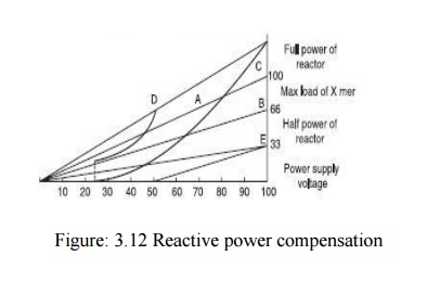
It should
be noted that the test transformer should be able to supply the maximum value
of load current for which it has been designed at all intermediate voltages
including the rated voltage. The power voltage characteristic is, therefore, a
straight line as shown by line A in
Fig. 3.14. The compensating reactive power absorbed by the air-cored inductor
is shown on parabolas B, C and D. These will be parabolas as the
reactive power = V2/X. Curve B corresponds to the condition
when the transformer primary is connected in parallel and the reactor is
connected at position 1 in Fig. 3.12.Similarly Curve C—Transformer primary connected in parallel and reactor at position
1 connected.
Curve D—Transformer primary connected in
series and reactor at position 2.When the primary series is connected, for the
same supply voltage, voltage per turn of primary becomes half its value when it
is parallel connected and, therefore, the secondary voltage becomes 1/2of the
rated voltage and hence the curve starts at 50% of the rated voltage. The power
of the voltage regulator is proportional to the supply voltage and, therefore,
is represented by line E in Fig. 3.12
and the maximum power at rated voltage is 33.3% of the maximum power
requirement of the transformer. All possible operating conditions of the test
transformer lie within the triangular area enclosed by the line A, the abscissa and the 100% rated
voltage line.
This area
has been sub-divided into different parts, so that the permissible supply power
(Here 33% of maximum transformer load) is never exceeded. The value of the
highest voltage is always taken for the evaluation of the compensation arrangement.
Since the impedance of the test transformer is usually large (about 20–25%),
the range under 25% of the rated voltage is not considered. It is clear from
the above considerations that the design of the compensating reactor depends
upon
· The power rating of the available regulator.
· The possibility of different connections of the winding of test transformer.
· The power rating of the test transformer.
In order
that the test laboratory meets all the different requirements, every particular
case must be investigated and a suitable reactor must be designed for reactive
power compensation. In multistage transformers with large power output, it is
desirable to provide reactive power Compensation at every stage, so that the
voltage stability of the test transformer is greatly improved.
Related Topics