Chapter: RF and Microwave Engineering : Microwave Tubes and Measurements
Q and Phase Shift
Q AND PHASE SHIFT
Microwave frequency can be measured by a number of different mechanical and electronic techniques.
ü Mechanical techniques
ü Slotted Line Method (Indirect Method)
The standing waves setup in a transmission line or a waveguide produce minima every half wavelength apart.
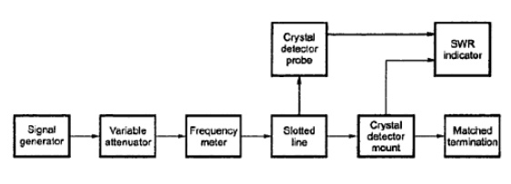
These minima are detected and the distance between them is measured. From which the wavelength and frequency can be calculated by

Resonant Cavity Method (Direct Method)
The most commonly used type of microwave frequency meter is wave meters. It consists of a cylindrical or coaxial resonant cavity. The size of the cavity can be altered by adjustable plunger. The cavity is designed in such a way that for a given position of the plunger, the cavity is resonant only at one frequency in the specified range.
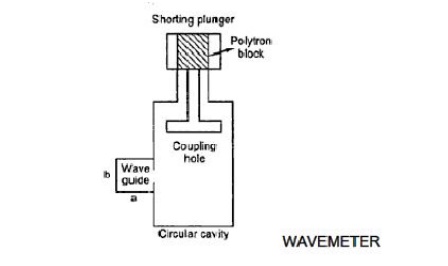
The cavity is coupled to the waveguide through an iris in the narrow wall of the waveguide. If the frequency of the wave passing through the waveguide is different from the resonance frequency of the cavity, the transmission is not affected. If these two frequencies coincide then the wave passing through the waveguide is attenuated due to power loss. It will be indicated as a dip in the meter.
Electronic Technique
Counter Method
An accurate measurement of microwave frequency can be measured here. The input signal is divided into two equal signals by a resistive power divider. These two parts of the signal are fed to 2 mixers. The mixer 1 is used in the input PLL (Phase Locked Loop) and the mixer 2 is used to determine the harmonic number. The frequency f1 of the input PLL is also fed to the direct counter circuits. The input PLL consists of a voltage controlled oscillator (VCO), mixer, an IF amplifier, a phase detector and a gain control block. The VCO searches over its range until an IF signal equal to 20MHz is found. Phase lock occurs when the phase detector output sets the VCO frequency f1 such that

where IF1 = 20 MHz at the phase lock and fx is the unknown frequency to be measured.
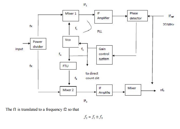
where f0 = 20 MHz offset frequency. This is done by a frequency translation unit (FTU). The frequency f2 drives the second sampler and produces a second output. IF2 is given as

By mixing IF2 with IF1 and rejecting 20 MHz and higher frequencies, nf0 is obtained. Counting the number of zero crossing for the period of f0, determines the harmonic number n of the phase lock loop. The input frequency is then calculated by presetting into IFref counter, measuring f1 and extending gate time according to number n.
Related Topics