Chapter: Mechanical : Metrology and Measurements : Laser Metrology
Computer Aided Inspection Using Robots
COMPUTER AIDED
INSPECTION USING ROBOTS
Robots can be used to carry out
inspection or testing operation for mechanical dimension physical
characteristics and product performance. Checking robot, programmable robot,
and co-ordinate robot are some of the types given to a multi axis measuring
machines. These machines automatically perform all the basic routines of a CNC
co ordinate measuring machine but at a faster rate than that of CMM. They are
not as accurate as p as CMM but they can check up to accuracies of
5micrometers. The co-ordinate robot can take successive readings at high speed and
evaluate the results using a computer graphics based real time statistical
analysis system.
Integration
of CAD/CAM with Inspection System
A product is designed, manufactured and
inspected in one automatic process. One of the critical factors is in
manufacturing equality assurance. The co-ordinate measuring machine assists in
the equality assurance function. The productivity can be improved by
interfacing with CAD/CAM system. This eliminates the labour, reduces
preparation time and increases availability of CMM for inspection. Generally
the CAD/CAM-CMM interface consists of a number of modules as given
(1)
CMM interface
This interface allows to interact with the CAD/CAM
database to generate a source file that can be converted to a CMM control data
file. During source file creation, CMM probe path motions are simulated and
displayed on the CAD/CAM workstation for visual verification. A set of CMM
command allow the CMM interface to take advantage of most of the CMM functional
capabilities. These command statement include set up, part datum control,
feature construction, geometric relations, tolerance, output control and
feature measurements like measurements of lines, points, arcs, circles,
splines, conics, planes, analytic surfaces.
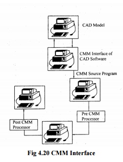
(2) Pre- processor
The pre-CMM processor
converts the language source file generated by CMM interface into the language
of the specified co ordinate measuring machine.
(3) Post-CMM processor
This creates wire frame surface model from the CMM-ASCII
output file commands are inserted into the ASCJI-CMM output file to control the
creation of CAD/CAM which include points, lines, arcs, circles, conics, splines
and analytic surfaces.
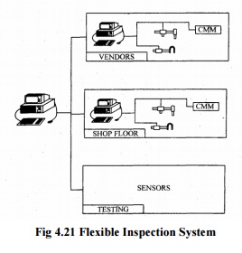
Flexible Inspection System
The block diagram of flexible inspection system is
shown in figure. This system has been developed and the inspection done at
several places in industry. This system helps product performance to improve
inspection and increase productivity. FIS is the Real time processor to handle
part dimensional data and as a multi programming system to perform
manufacturing process control. The input devices used with this system are
CMM’s;

Microprocessor based gauges and other inspection
devices. The terminal provides interactive communication with personal
computers where the programmes are stored. The data from CMMs and other
terminals are fed into the main computer for analysis and feedback control. The
equality control data and inspection data from each station are fed through the
terminals to the main computer. The data will be communicated through telephone
lines. Flexible inspection system involves more than one inspection station.
The objective of the flexible inspection system is to have off time multi
station automated dimensional verification system to increase the production
rate and less inspection time and to maintain the inspection accuracy and data
processing integrity.
Machine
Vision
A Vision system can be defined as a system for
automatic acquisition and analysis of images to obtain desired data for
interpreting or controlling an activity. It is a technique which allows a
sensor to view a scene and derive a numerical or logical decision without
further human intervention. Machine vision can be defined as a means of
simulating the image recognition and analysis capabilities of the human system
with electronic and electro mechanical techniques. Machine vision system are
now a days used to provide accurate and in expensive 100% inspection of work
pieces. These are used for functions like gauging of dimensions, identification
of shapes, measurement of distances, determining orientation of parts,
quantifying motion-detecting surface shading etc. It is best suited for high
production. These systems function without fatigue. This is suited for
inspecting the masks used in the production of micro-electronic devices.
Standoff distance up to one meter is possible.
Vision
System
The schematic diagram of a typical
vision system is shown. This system involves image acquisition; image
processing Acquisition requires appropriate lighting. The camera and store
digital image processing involves manipulating the digital image to simplify
and reduce number of data points. Measurements can be carried out at any angle
along the three reference axes x y and z without contacting the part. The
measured values are then compared with the specified tolerance which stores in
the memory of the computer.
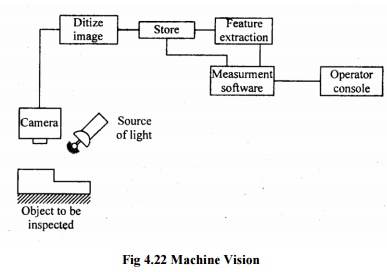
Fig
4.22 Machine Vision
The main advantage of vision system is
reduction of tooling and fixture costs, elimination of need for precise part
location for handling robots and integrated automation of dimensional
verification and defect detection.
Principle
Four
types of machine vision system and the schematic arrangement is shown
(i) Image
formation.
(ii) Processing
of image in a form suitable for analysis by computer.
(iii) Defining
and analyzing the characteristic of image.
(iv)Interpretation
of image and decision-making.
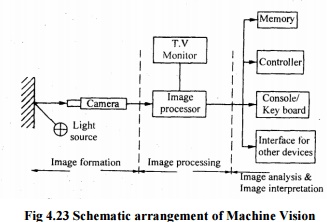
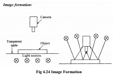
Fig
4.24 Image Formation
For formation of image suitable light
source is required. It consists of incandescent light, fluorescent tube, fiber
optic bundle, and arc lamp. Laser beam is used for triangulation system for
measuring distance. Ultraviolet light is used to reduce glare or increase
contrast. Proper illumination back lighting, front lighting, structured light
is required. Back lighting is used to obtain maximum image contrast. The
surface of the object is to be inspected by using front lighting. For
inspecting three-dimensional feature structured lighting is required. An image
sensor vidicon camera, CCD camera is used to generate the electronic signal
representing the image. The image sensor collects light from the scene through
a lens, using photosensitive target, converts into electronic signal.
Vidicon
camera
Image is formed by focusing the incoming light
through a series of lenses onto the photoconductive faceplate of the vidicon
tube. The electron beam scans the photoconductive surface and produces an
analog voltage proportional to the variation in light intensity for each scan
line of the original scene.
Solid-state
camera
The image sensors change coupled device (CCD)
contain matrix of small array, photosensitive elements accurately spaced and
fabricated on silicon chips using integrated circuit technology. Each detector
converts in to analog signal corresponding to light intensity through the
camera lens.
Image
processor
A camera may form an image 30 times per
sec at 33 m sec intervals. At each time interval the entire image frozen by an
image processor for processing. An analog to digital converter is used to
convert analog voltage of each detector in to digital value. If voltage level
for each pixel is given by either 0 or I depending on threshold value. It is called
binary system on the other hand grey scale system assigns upto 256 different
values depending on intensity to each pixel. Grey scale system requires higher
degree of image refinement, huge storage processing capability. For analysis
256 x 256 pixels image array up to 256 different pixel values will require
65000-8 bit storage locations at a speed of 30 images per second. Techniques
windowing and image restoration are involved.
Windowing
Processing
is the desired area of interest and ignores non-interested part of image.
Image
restoration
Preparation of image during the
pre-processing by removing the degrade. Blurring of lines, poor contrast
between images and presence of noise are the degrading.
The
quality may be improved
1) By
improving the contrast by brightness addition.
2) By
increasing the relative contrast between high and low intensity elements.
3) By
Fourier domain processing.
4) Other
techniques to reduce edge detection and run length encoding.
Image
Analysis
Digital image of the object formed is
analyzed in the central processing Unit of the system. Three important tasks
performed by machine vision system are measuring the distance of an object from
a vision system camera, determining object orientation and defining object
position. The distance of an object from a vision system camera can be
determined by triangulation technique. The object orientation can he
determined by the methods of equivalent ellipse. The image can be
interpreted by two-dimensional image. For complex three-dimensional objects
boundary locations are determined and the image is segmented into distinct
region.
Image
Interpretation
This involves identification of on
object. In binary system, the image is segmented on the basis of white and
black pixels. The complex images can he interpreted by grey scale technique and
algorithms. The most common image interpretation is template matching.
Function of Machine
Vision
· Lighting
and presentation of object to evaluated.
· It
has great compact on repeatability, reliability and accuracy.
· I.ighting
source and projection should be chosen and give sharp contrast.
· Images
sensor compressor TV camera may he vidicon or solid state.
· For
simple processing, analog comparator and a computer controller to convert the
video information to a binary image is used.
· Data
compactor employs a high speed away processor to provide high speed processing
of the input image data.
·
System control computer communicates
with the operator and make decision about the part being inspected.
·
The output and peripheral devices
operate the control of the system. The output enables the vision system to
either control a process or provide caution and orientation information two a
robot, etc.
·
These operate under the control of the
system control of computer.
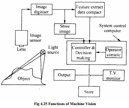
Fig
4.25 Functions of Machine Vision
Applications
· Machine
vision can he used to replace human vision fur welding. Machining and
maintained relationship between tool and work piece and assembly of parts to
analyze the parts.
This
is frequently used for printed circuit board inspection to ensure minimum conduction
width and spacing between conductors. These are used for weld seam tracking,
robot guideness and control, inspection of microelectronic devices and tooling,
on line inspection in machining operation, assemblies monitoring high-
speed
packaging equipment etc.
·
It gives recognition of an object from
its image. These are designed to have strong geometric feature interpretation
capabilities and pa handling equipment.
Related Topics