Chapter: Mechanical Engineering : Power Plant Engineering
Centrifugal Pumps
CENTRIFUGAL PUM PS
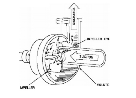
1 COMPONENTS OF CENTRIFUGAL PUMP:
A rotating component comprising of
an impeller and a shaft.
A stationery compon ent comprising a
volute (casing), suction and de livery pipe.
2 WORKING PRI NCIPLE OF CENTRIFUGAL PUMP:
Principle:
When a certain mass of fluid is rotated by an external source,
it is thr own away from the central axis of rotation and a centrifugal head is
impressed which ena bles it to rise to a higher level.
Working:
The delivery valve is closed and the pump is primed,
so that no air po cket is left.
Keeping the delivery valve still closed the electric
motor is start ed to rotate the impeller.
• The
rotation of the impeller is gradually increased till the impeller rotates at
its normal speed.
• After
the impeller attains the normal speed the delivery valve is o pened when the
liquid is sucked continuously upto the suction pipe.
• It
passes through the eye of the casing and enters the impeller at its c entre.
• The
liquid is impelle d out by the rotating vanes and it comes out at the outlet
tips of the vanes into the casing.
·
Due to the impeller action the pressure head
as well as the velocity heads are increased.
·
From the casing the liquid passes into the
pipe and lifted to the required height.
·
When pump is to be stopped the delivery valve is
to be first closed, otherwise there may be some backflow of water into the
reservoir.
Types of
casing
Volute
and Vortex Casing
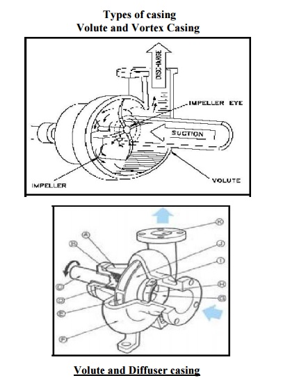
Volute Casing: In this
type of casing the area of flow gradually increases from the impeller outlet
to the delivery pipe.
Vortex Casing:
If a circular chamber is provided
between the impeller and volute chamber the casing is known as Vortex Chamber.
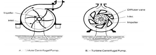
Diffuser C :
·
The impeller is surrounded by a diffuser.
·
The guide vanes are designed in such a way
that the water from the impeller enters the guide vanes without shock.
·
It reduces the vibration of the pump.
·
Diffuser casing, the diffuser and the outer
casing are stationery parts.
Priming of a centrifugal Pump:
The operation of filling the suction pipe, casing and a
portion of delivery pipe with the liquid to be raised, before starting the pump
is known as Priming
It is done to remove any air, gas
or vapour from these parts of pump.
If a Centrifugal pump is not primed before starting air
pockets inside impeller may give rise to vortices and causes discontinuity of
flow
Losses in Centrifugal pump:
Hydraulic Losses:
Shock or eddy losses at the entrance to and exit from the
impeller Losses due to friction in the impeller
Friction and eddy losses in the guide vanes/diffuser and casing
Mechanical Losses:
·
Losses due to disc friction between the
impeller and the liquid which fills the clearance spaces between the impeller
and casing
·
Losses pertaining to friction of the main
bearing and glands.
Specific speed of Centrifugal Pump:
It is the speed in revolutions per minute at which a
geometrically similar impeller would deliver one cubic meter of liquid per
second against a delivery head of one meter.
Related Topics