Chapter: Basic Electrical and electronics : Foundamentals of Communication Enginnering
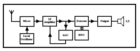
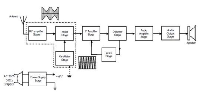
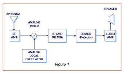
Block diagram of radio
Block diagram of radio
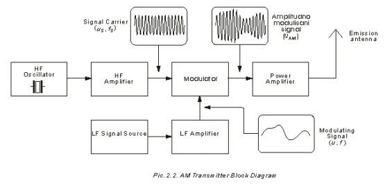
AM Transmitter
In order to better understand the way the radio transmitter works, block - diagram of a simple AM (amplitude modulated) signal transmitter is shown on Pic. The amplitude modulation is being performed in a stage called the modulator. Two signals are entering it: high frequency signal called the carrier (or the signal carrier), being created into the HF oscillator and amplified in the HF amplifier to the required signal level, and the low frequency (modulating) signal coming from the microphone or some other LF signal source (cassette player, record player, CD player etc.), being amplified in the LF amplifier. On modulator's output the amplitude modulated signal UAM is acquired. This signal is then amplified in the power amplifier, and then led to the emission antenna.
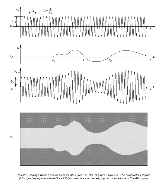
The shape
and characteristics of the AM carrier, being taken from the HF amplifier into
the modulator, are shown on Pic. As you can see, it is a HF voltage of constant
amplitude US and frequency fS. On Pic. the LF signal that appears at the input
of the modulator at the moment t0 is shown. With this signal the modulation of
the carrier's amplitude is being performed, therefore it is being called the
modulating signal. The shape of the AM signal exiting the modulator is shown on
Pic. From the point t0 this voltage has the same shape as that on Pic. From the
moment t0 the amplitude of AM signal is being changed in accordance with the
current value of the modulating signal, in such a way that the signal envelope
(fictive line connecting the voltage peaks) has the same shape as the
modulating signal.
Let's
take a look at a practical example. Let the LF signal on Pic. be, say, an
electrical image of the tone being created by some musical instrument, and that
the time gap between the points t0 and t2 is 1 ms. Suppose that carrier
frequency is fS=1 MHz (approximately the frequency of radio Kladovo, exact
value is 999 kHz). In that case, in period from t0 till t2 signals us on Pic.
and AM on should make a thousand oscillations and not just eighteen, as shown
in the picture. Then It is clear that it isn't possible to draw a realistic
picture, since all the lines would connect into a dark spot. The true picture
of AM signal from this example is given on Pic. That is the picture that appears
on screen of the oscilloscope, connected on the output of the modulator: light
coloured lines representing the AM signal have interconnected, since they are
thicker than the gap between them.
Block -
diagram on Pic is a simplified schematic of an AM transmitter. In reality there
are some additional stages in professional transmitters that provide the
necessary work stability, transmitter power supply, cooling for certain stages
etc. For simple use, however, even simpler block diagrams exist, making the completion
of an ordinary AM transmitter possible with just a few electronic components.
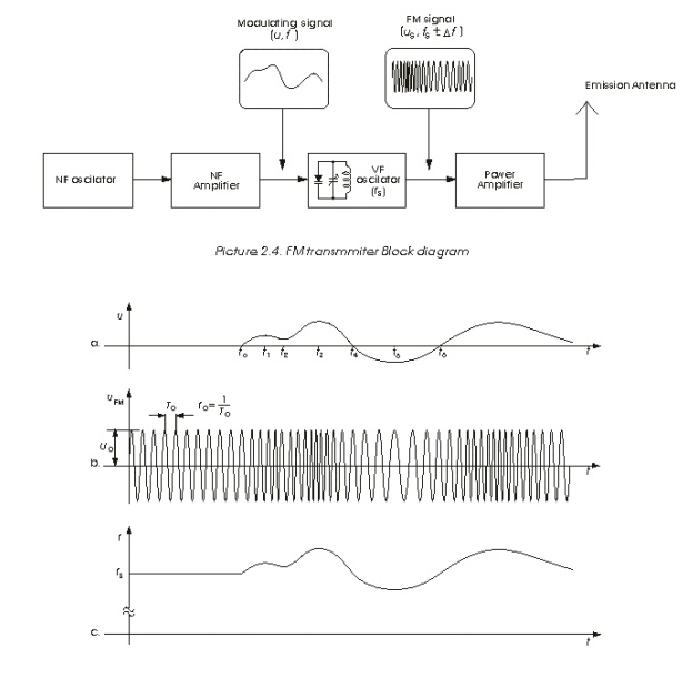
FM Transmitter
Block
diagram of an FM (frequency modulated) transmitter is given on Pic.2.4.
Information being transferred, i.e. the modulating signal, is a signal from
some LF source. it is being amplified in LF amplifier and then led into the HF
oscillator, where the carrier signal is being created. The carrier is a HF
voltage of constant amplitude, whose frequency is, in the absence of modulating
signal, equal to the transmitter's carrier frequency fS. In the oscillatory
circuit of the HF oscillator a varicap (capacitive) diode is located. It is a
diode whose capacitance depends upon the voltage between its ends, so when
being exposed to LF voltage, its capacitance is changing in accordance with
this voltage. Due to that frequency of the oscillator is also changing, i.e.
the frequency modulation is being obtained. The FM signal from the HF
oscillator is being proceeded to the power amplifier that provides the
necessary output power of the transmission signal. Voltage shapes in FM
transmitter are given on Pic.2.5. Pic.2.5-a shows the LF modulating signal. The
frequency modulation begins at moment t0 and the transmission frequency begins
to change, as shown on Pic.2.5-b: Whilst current value of the LF signal is
raising so is the trasmitter frequency, and when it is falling the frequency is
also falling. As seen on Pic.2.5-c, the information (LF signal) is being
implied in frequency change of the carrier.
The
carrier frequencies of the radio difusion FM transmitters (that emmit the
program for "broad audience") are placed in the waveband from 88 MHz
til 108 MHz, the maximum frequency shift of the transmitter (during the
modulation) being ±75 kHz. Because of that the FM signal should be drawn much
"thicker", but it would result in a black-square-shaped picture.
AM radio broad cast transmitter
AM
broadcasting is the process of radio broadcasting using amplitude modulation
(AM). AM was the first method of impressing sound on a radio signal and is
still widely used today. Commercial and public AM broadcasting is authorized in
the medium wave band worldwide, and also in parts of the long wave and short
wave bands. Radio broadcasting was made possible by the invention of the
amplifying vacuum tube, the Audion(triode), by Lee de Forest in 1906, which led
to the development of inexpensive vacuum tube AM radio receivers and
transmitters during World War I. Commercial AM broadcasting developed from
amateur broadcasts around 1920, and was the only commercially important form of
radio broadcasting until FM broadcasting began after World War II. This period
is known as the "Golden Age of Radio". Today, AM competes with FM, as
well as with various digital radio broadcasting services distributed from
terrestrial and satellite transmitters. In many countries the higher levels of
interference experienced with AM transmission have caused AM broadcasters to
specialize in news, sports and talk radio, leaving transmission of music mainly
to FM and digital broadcasters.
AM radio
technology is simpler than frequency modulated (FM) radio, Digital Audio
Broadcasting (DAB), satellite radio or HD (digital) radio. An AM receiver
detects amplitude variations in the radio waves at a particular frequency.
It then
amplifies changes in the signal voltage to drive aloudspeaker or earphones.
The
earliest crystal radio receivers used a crystal diode detector with no
amplification, and required no power source other than the radio signal itself.
In North
American broadcasting practice, transmitter power input to the antenna for
commercial AM stations ranges from about 250 to 50,000watts. Experimental
licenses were issued for up to 500,000 watts radiated power, for stations
intended for wide-area communication during disasters. One such superstation
was Cincinnati station WLW, which used such power on occasion before World War
II. WLW's superpower transmitter still exists at the station's suburban transmitter
site, but it was decommissioned in the early 1940s and no current commercial
broadcaster in the U.S. or Canada is authorized for such power levels. Some
other countries do authorize higher power operation (for example the Mexican
station XERF formerly operated at 250,000 watts).
Antenna design must consider the coverage desired and stations may be required, based on the terms of their license, to
directionalize their transmitted signal to avoid interfering with other
stations operating on the same frequency.
Radio receiver
In the
early days of what is now known as early radio transmissions, say about 100
years ago, signals were generated by various means but only up to the L.F.
region.
Communication
was by way of morse code much in the form that a short transmission denoted a
dot (dit) and a longer transmission was a dash (dah). This was the only form of
radio transmission until the 1920's and only of use to the military, commercial
telegraph companies and amateur experimenters.
Then it
was discovered that if the amplitude (voltage levels - plus and minus about
zero) could be controlled or varied by a much lower frequency such as A.F. then
real intelligence could be conveyed e.g. speech and music. This process could
be easily reversed by simple means at the receiving end by using diode
detectors. This is called modulation and obviously in this case amplitude
modulation or A.M.
This
discovery spawned whole new industries and revolutionized the world of
communications. Industries grew up manufacturing radio parts, receiver
manufacturers, radio stations, news agencies, recording industries etc.
Disadvantages to A.M. radio
Firstly
because of the modulation process we generate at least two copies of the
intelligence plus the carrier. For example consider a local radio station
transmitting on say 900 Khz. This frequency will be very stable and held to a
tight tolerance. To suit our discussion and keep it as simple as possible we
will have the transmission modulated by a 1000 Hz or 1Khz tone.
At the
receiving end 3 frequencies will be available. 900 Khz, 901 Khz and 899 Khz
i.e. the original 900 Khz (the carrier) plus and minus the modulating frequency
which are called side bands. For very simple receivers such as a cheap transistor radio we only
require the original plus either one of the side bands. The other one is a
total waste. For sophisticated receivers one side band can be eliminated.
The net
effect is A.M. radio stations are spaced 10 Khz apart (9 kHz in Australia) e.g.
530 Khz...540 Khz...550 Khz. This spacing could be reduced and nearly twice as
many stations accommodated by deleting one side band. Unfortunately the
increased cost of receiver complexity forbids this but it certainly is
feasible.
Related Topics