Chapter: Mobile Networks : Wireless Networks
Wi-MAX(Worldwide Interoperability for Microwave Access)
WI-MAX
Wi-MAX (Worldwide Interoperability for Microwave
Access) unites the technologies of wireless and broadband to provide high-speed
internet access across long distances. The name was christened by WiMAX Forum
that promotes interoperability and conformity of the standard. The forum
defines the technology as "a standards-based technology enabling the
delivery of last mile wireless broadband access as an alternative to cable and
DSL". With the guarantee of WiMAX Forum the vendors are authorized to sell
their WiMAX certified products so they can enjoy operability with other
products of same type. It is a telecommunication protocol capable of providing
internet access to fixed and mobile users. For an outstanding performance like
Wi-Fi networks along with QOS (Quality of Service) and coverage this Wireless
Broadband Access (BAS) technology is assembled around IP (internet protocol).
Currently it offers 40 Mbit/s but expected to offer 1 Gbit/s speed for fixed
users.
WI-MAX ARCHITECTURE
There are
three main components of WiMax network architecture.
·
The first component is the mobile stations which
are used as a source of network connection for end user.
·
The second network is an access service network
which is formed of more than two or three base stations. It also contains ASN
gateways which build the radio access at the end.
·
The third component is connectivity service network
which is responsible for providing IP functions. The base station provides the
air interface for the mobile stations. The base stations also provide mobile
management functions, triggering and tunnel establishment, radio resource
management, dynamic host control protocol proxy, quality of service enforcement
and multicast group management. ASN is responsible for radio resource
management, encryption keys, routing to the selected network and client
functionality. Connectivity service network is responsible for internet
connections, corporate and public networks and many other user services.
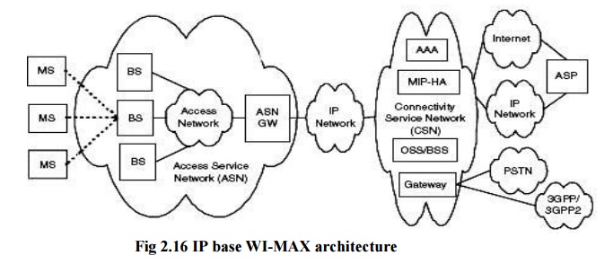
Standard WiMax Architecture
The WiMax network is based on three four basic components they are:
3. AS gateway, 4. CSN and 5. MS.
The basic network has a inner IP core which is
bounded by an ASN gateway, which is associated to service network or CSN. The
main IP core is attach to the internet backbone for aid and coverage. The WiMax
network which is also part of the ISP network is recognized as access service
gateway. This ASN handles the micro and macro base stations, which offer WiMax
access to end users. The connectivity examine network or CSN is an important
part of WiMax architecture which provides the verification to the user devices.
CSN is in charge for providing roaming among the
network service providers. It is CSN which is accountable for user security and
quality for service for this reason it uses several protocols. The IP address
management is also handled by CSN. IP core is in the middle of CSN and ASN. CSN
provides the internet and telecommunications connectivity. ASP communicates to
the base stations and the mobile stations. At the users end the WiMax
architecture may additionally contain firewall for security. WiMax architecture
provides discretion at user end to make possible amendments.
Two Dimensions of WiMax Network
WiMax network is composed of two parts the 1. WiMax
tower 2. WiMax receiver.
WiMax tower is associated straightly to the
internet backbone using a wired connection such as optical fiber. It can be
linked to the WiMax tower using a line of sight link or a non line of sight
link. The line of site communiqué involves the use of fixed antenna or dish.
This antenna is unchanging or deployed on the roof top or the tower of the
building. Line of sight connection is measured as more strong and stable
connection. Thus it sends lot of error free data over the network. It uses a
frequency range of 66Ghz. Higher frequency reduces the possibility of signal
flaw and interference and provides extra bandwidth. On the other hand the non
line of sight link provides you connectivity with the fixing of small antenna
in your PC. This mode provides lower frequency range from 2 GHz to 11 GHz. The
lower band signals are not prone to obstacles like trees and walls. Hence the
signal
strength
is more and the user receives the quality of service. For every WiMax
connectivity and architecture it is significant to connect to an internet
backbone via swift wired connection.
L2CAP-LOGICAL LINK CONTROL AND ADAPTION PROTOCOL:
The L2CAP
is a data link control protocol.The L2CAP link layer operates over an ACL link
provided by the baseband. A single ACL link, set up by the link manager using
LMP, is always available between the master and any active slave. This provides
a point-to-multipoint link supporting both asynchronous and isochronous data
transfer. L2CAP provides services to upper-level protocols by transmitting data
packets over L2CAP channels. Three types of L2CAP channels exist: bidirectional
signaling channels that carry commands; connection-oriented channels for
bidirectional point-to-point connections; and unidirectional connectionless
channels that support point-to multipoint connections, allowing a local L2CAP
entity to be connected to a group of remote devices.
Functions:
It
Performs 4 major functions
·
Managing the creation and termination of logical
links for each connection through ―channel‖ structures
·
Enforcing and defining QoS requirements
·
Adapting Data, for each connection, between
application (APIs) and Bluetooth Baseband formats through Segmentation and
Reassembly (SAR)
·
Performing Multiplexing to support multiple
concurrent connections over a single common radio interface.
Channels:
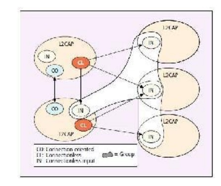
L2CAP CHANNELS
The above
figure shows L2CAP entities with various types of channels between them. Every
L2CAP channel includes two endpoints referred to by a logical channel
identifier (CID). Each CID may represent a channel endpoint for a connection
oriented channel, a connectionless channel, or a signaling channel. Since a
bi-directional signaling channel is required between any two L2CAP entities
before communication can take place, every L2CAP entity will have one signaling
channel endpoint with a reserved CID of 0x0001. All signal channels between the
local L2CAP entity and any remote entities use this one endpoint. Each
connection-oriented channel in an L2CAP entity will have a local CID that is
dynamically allocated. All connection-oriented
CIDs must
be connected to a single channel, and that channel must be configured before
data
transfer
can take place. Note that the channel will at that point be bound to a specific
upper level
protocol.
In addition, a quality of service (QoS) agreement for the channel will be
established
between
the two devices. QoS is negotiated for each channel during configuration and
includes data flow parameters such as peak bandwidth, as well as the
transmission type: best effort, guaranteed, or no traffic. Connectionless
channels are unidirectional and used to form groups. A single outgoing
connectionless CID on a local device may be logically connected to multiple
remote devices.
The
devices connected to this outgoing endpoint form a logical group. These
outgoing CIDs are dynamically allocated. The incoming connectionless CID,
however, is fixed at 0x0002. Although multiple outgoing CIDs may be created to
form multiple logical groups, only one incoming connectionless CID is provided
on each L2CAP entity. All incoming connectionless data arrives via this
endpoint. These channels do not require connection or configuration. Therefore,
any required configuration information, such as upper-level protocol, is passed
as part of the data packet.
Functional requirement:
Protocol
multiplexing distinguishes between upper-layer protocols like SDP, RFCOMM. It
Segments larger packets from higher layers into smaller baseband packets. It
allows QoS parameters to be exchanged during connection establishment and it
also allows efficient mapping of protocol groups to piconets.
L2CAP Operation:
L2CAP
channel end-points are represented by channel identifiers (CIDs). An L2CAP
channel is uniquely defined by 2 CIDs and device addresses. Reserved CIDs
0x0001:
Signaling channel
0x0002:
Connection-less reception
0x0003-0x003F:
Reserved for future use
Operation between layers:
It
transfers data between higher layer protocols and lower layer protocols. It
Signal with peer L2CAP implementation. L2CA layer should be able to accept events from lower/upper layers. L2CA
layer should be able to take appropriate
actions in response to these events.
L2CAP Format
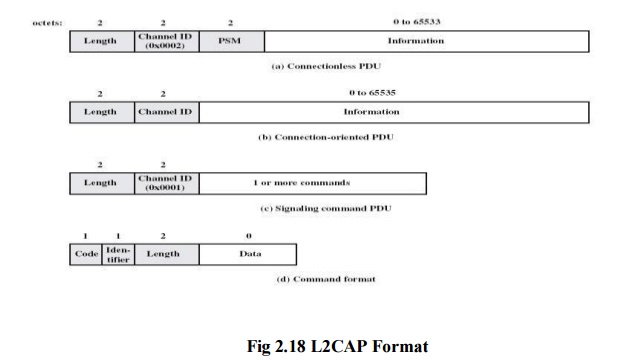
L2CAP Frame field for connectionless service:
Length –
It indicates length of information payload, PSM fields Channel ID – 2,
indicating connectionless channel
Protocol/service
multiplexer (PSM) – identifies higher-layer recipient for payload
Not
included in connection-oriented frames Information payload – higher-layer user
data
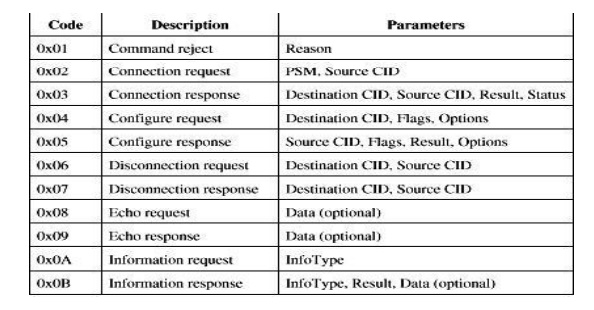
Signaling frame payload:
It Consists of one or more L2CAP commands, each
with four fields Code – identifies type of command
Identifier
– used to match request with reply
Length –
length of data field for this command
Data –
additional data for command, if necessary
L2CAP signaling command codes: