Chapter: Mobile Networks : Wireless Networks
System Architecture
SYSTEM ARCHITECTURE
Wireless
networks can exhibit two different basic system architectures as
infrastructure-based or ad-hoc. Figure shows the components of an
infrastructure and a wireless part as specified for IEEE 802.11. Several nodes,
called stations (STAi), are connected to access points (AP). Stations are
terminals with access mechanisms to the wireless medium and radio contact to
the AP. The stations and the AP which are within the same radio coverage form a
basic service set (BSSi). The example shows two BSSs – BSS1 and BSS2 – which
are connected via a distribution system. A distribution system connects several
BSSs via the AP to form a single network and thereby extends the wireless
coverage area. This network is now called an extended service set (ESS) and has
its own identifier, the
ESSID.
The ESSID is the ‗name‘ of a network and is used to separate different
networks. Without knowing the ESSID (and assuming no hacking) it should not be
possible to participate in the WLAN. The distribution system connects the
wireless networks via the APs with a portal, which forms the interworking unit
to other
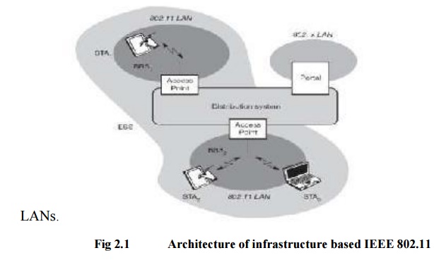
The
architecture of the distribution system is not specified further in IEEE
802.11. It could consist of bridged IEEE LANs, wireless links, or any other
networks. However, distribution system services are defined in the standard
Stations can select an AP and associate with it. The APs support roaming (i.e.,
changing access points), the distribution system handles data transfer between
the different APs. APs provide synchronization within a BSS, support power
management, and can control medium access to support time-bounded service. In
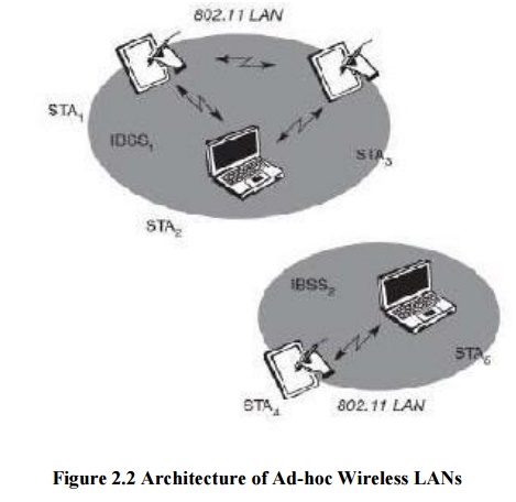
addition to infrastructure-based networks, IEEE 802.11 allows the building of
ad-hoc networks between stations, thus forming one or more independent BSSs
(IBSS) as shown in Figure 7.4. In this case, an IBSS comprises a group of
stations using the same radio frequency. Stations STA1, STA2, and STA3 are in
IBSS1, STA4 and STA5 in IBSS2. This means for example that STA3 can communicate
directly with STA2 but not with STA5. Several IBSSs can either be formed via
the distance between the IBSSs or by using different carrier frequencies (then
the IBSSs could overlap physically). IEEE 802.11 does not specify any special
nodes that support routing, forwarding of data or exchange of topology
information as, e.g., HIPERLAN 1 or Bluetooth.