Chapter: Mobile Networks : Wireless Networks
HIPERLAN(high performance local area network)
HIPERLAN
INTRODUCTION
HIPERLAN
stands for high performance local area
network. It is a wireless standard derived from traditional LAN
environments and can support multimedia and asynchronous data effectively at
high data rates of 23.5 Mbps. It is primarily a European standard alternative
for the IEEE 802.11 standards and was published in 1996. It is defined by the
European Telecommunications Standards Institute (ETSI). It does not necessarily
require any type of access point infrastructure for its operation, although a
LAN extension via access points can be implemented.
Radio
waves are used instead of a cable as a transmission medium to connect stations.
Either, the radio transceiver is mounted to the movable station as an add-on
and no base station has to be installed separately, or a base station is needed
in addition per room. The stations may be moved during operation-pauses or even
become mobile. The maximum data rate for the user depends on the distance of
the communicating stations. With short distance(<50 m) and asynchronous
transmission a data rate of 20 Mbit/s is achieved, with up to 800 m distance a
data rate of 1 Mbit/s are provided. For connection-oriented services, e.g.
video-telephony, at least 64 kbit/s are offered.
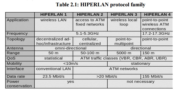
HIPERLAN uses cellular-based data networks to connect to an ATM backbone. The main idea behind HIPERLAN is to provide an infrastructure or ad-hoc wireless with low mobility and a small radius. HIPERLAN supports isochronous traffic with low latency. The HiperLAN standard family has four different versions.
The key feature of all four networks is their integration of time-sensitive data transfer services. Over time, names have changed and the former HIPERLANs 2,3, 1nd 4 are now called HiperLAN2, HIPERACCESS, and HIPERLINK.
1. HIPERLAN 1
Planning
for the first version of the standard, called HiperLAN/1, started 1991, when
planning of 802.11 was already going on. The goal of the HiperLAN was the high
data rate, higher than 802.11. The standard was approved in 1996. The
functional specification is EN300652, the rest is in ETS300836.
The
standard covers the Physical layer and the Media Access Control part of the
Data link layer like 802.11. There is a new sub layer called Channel Access and
Control sub layer (CAC). This sub layer deals with the access requests to the
channels. The accomplishing of the request is dependent on the usage of the
channel and the priority of the request.
CAC layer
provides hierarchical independence with Elimination-Yield Non-Preemptive
Multiple Access mechanism (EY-NPMA). EY-NPMA codes priority choices and other
functions into one variable length radio pulse preceding the packet data.
EY-NPMA enables the network to function with few collisions even though there
would be a large number of users. Multimedia applications work in HiperLAN
because of EY-NPMA priority mechanism. MAC layer defines protocols for routing,
security and power saving and provides naturally data transfer to the upper
layers.
On the
physical layer FSK and GMSK modulations are used in HiperLAN/1. HiperLAN
features:
range
50 m
slow
mobility (1.4 m/s)
supports
asynchronous
and synchronous traffic
sound
32 kbit/s, 10 ns latency
video
2 Mbit/s, 100 ns latency
data
10 Mbit/s
HiperLAN
does not conflict with microwave and other kitchen appliances, which are on 2.4
GHz.
Elimination-yield non-preemptive
priority multiple access (EY-NPMA)
EY-NPMA
is a contention based protocol that has been standardized under ETSI‘s
HIPERLAN,
a standard for wireless LANs. Unlike other contention based protocols, EY-NPMA
provides excellent support for different classes of traffic regarding quality
of service and demonstrates very low collision rates. EY-NPMA is the medium
access mechanism used by HIPERLAN Type 1. It uses active signaling.
Active
signaling takes advantage of the fact that the current wireless technology
enables us to have a slot time very much smaller than the average packet size.
Each node that wants to access the medium transmits a non-data preamble pattern
consisting of slots. This pattern is made up of alternating idle and busy
periods of different lengths (measured in slots). Conflict resolution and
collision detection is done during this preamble. The main rule is that if a
node detects a signal during one of its listening periods in its pattern, it aborts
and defers until the next cycle. Otherwise, the node transmits its packet at
the end of the pattern transmission.
With
EYNPMA, each station may attempt to access the channel when a condition out of
a group of three is met. The three conditions are:
Channel free condition
Synchronized channel conditio
Hidden elimination condition
The channel free condition occurs when the channel
remains idle for at least a predefined time interval. A station willing to
transmit senses the channel for this time interval, the station extends its
period of sensing by a random number of slots (backoff). If the channel is
still sensed as idle during the backoff period, the station commences
transmitting. In both modes of operation unicast transmissions must get positively
acknowledged or else the transmission is declared erroneous. Multicast and
broadcast packets are not acknowledged.
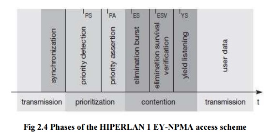
The synchronized channel condition occurs when the
channel is idle in the channel synchronization interval, which starts
immediately after the end of the previous channel access cycle. The
synchronized channel access cycle consists of three distinct phases:
Prioritization
Contention(Elimination
and Yield) Transmission
Important
features of the EY-NPMA
5.
No preemption by frames with higher priority after
the priority resolution possible.
6. Hierarchical
independence of performance.
7. Fair
contention resolution of frames with the same priority
In
prioritization, EY-NPMA recognizes five distinct priorities from 0 to 4, with 0
being the highest priority. The cycle begins with each station having data to
transmit sensing the channel for as many slots as the priority of the packet in
its buffer. All stations that successfully sense the channel as idle for the
whole interval proceed to the next phase, the elimination phase.
During
the elimination phase, each station transmits an energy burst of random length.
These bursts ensure that only the stations having the highest priority data at
a time proceed to the elimination phase. The length of the energy burst is a
multiple of slots up to a predefined maximum. As soon as a station finishes
bursting, it immediately senses the channel. If the channel is sensed as idle,
the station proceeds to the next phase. Otherwise, it leaves the cycle.
During
the yield phase, the station that survived the two previous ones, back off for
a random number of slots. The station that backs off for the shortest interval
eventually gets access of the channel for data transmission. All other station
sense the beginning of the transmission and refrain from transmitting.
a) Prioritization Phase
Prioritization
Phase is the first attempt at reducing the number of contenders for the
channel. Every contender calculates the number of idle slots according to the
priority of its data, and senses the channel during those slots. Contenders
with highest priority data will have no idle slots, while those with lowest
priority data will have all idle slots If it detects a signal during those idle
slots, it defers until the next cycle. This means that only the higher priority
contenders survive. If it does not detect a signal during these idle slots, it
sends the priority pulse and enters the elimination phase. In the first phase
of the synchronized channel access cycle, known as the Prioritization Phase,
every node allows a number of idle slots, where the default slot length is 168
high rate bit-periods.
The
number of the idle slots is equal to the arithmetic value of the CAM priority
of the packet. Every contending node senses the channel, while it allows the
idle slots. If it detects a signal transmission, it defers, that is it quits
the effort to gain access to the channel and waits for the next channel access
cycle to try to transmit. When a node detects no transmission during the
Prioritization Phase, it transmits a pulse right after the idle slots, and
proceeds to the next phase. This pulse is the one listened by every ―defeated‖
node. The nodes that proceed to the next contention phase have a packet to send
of the same highest CAM priority.
b) Elimination Phase
Elimination
Phase is the second attempt at reducing the contenders. This phase consists of
extending the priority pulse with a randomly calculated number of busy slots.
The number of slots is independently calculated for each node. The
probability
of a larger than k-slot pulse is 1/2k. Therefore, the probability of
a larger than 1-slot pulse is 1/2, larger than a 2-slot pulse is 1/4 and so on.
Immediately after this pulse, the node senses the channel. If the channel is
busy, it defers transmission until the next cycle. If the channel is idle, it
enters the yield phase.
The nodes
that ―survive‖ the Prioritization Phase keep on trying to gain access to the
channel. The objective of this medium access mechanism is to eliminate as more
contending nodes as possible, but of course not all of them. During the
Elimination Phase, a great percentage of the contending nodes is eliminated,
but at least one of them survives. Every node that has not been defeated during
the Prioritization Phase transmits an elimination pulse which is actually the
lengthening of the priority pulse. Right after the end of this pulse, the nodes
allow an idle slot, which is called survival verification slot, during which
they sense the channel.
If a node
detects a transmission during this time interval, this means that the specific
node is ―defeated‖, so it defers. Thus, the nodes that survive the Elimination
Phase carry the packets of the highest priority and they have transmitted the
longest elimination pulse.
Yield Phase
Yield
Phase is the last phase of EY-NPMA, and is the last try to reduce collisions.
Only the nodes that have survived elimination phase start the yield phase. The
node selects a random number of idle slots uniformly distributed between 0 and
9. At the end of the yield phase, the node again senses the channel. If the
channel is idle, it starts its transmission.
Yield
Phase is the last phase before the transmission of a data packet and it is the
last effort to reduce the number of the contending nodes. The nodes that have
survived the Elimination Phase enter the Yield Phase allowing a number of idle slots.
Every node that detects transmission during these slots quits the current
effort to gain access to the channel and waits till the next channel access
cycle. If a node detects no transmission, it eventually transmits its data
packet. Thus, a node
―loses‖
in Yield Phase, when it listens some other node transmitting a data packet.
The
number of the idle slots is random and uniformly distributed between 0 and 9.
WATM
In the
last decade of the twentieth century, technological improvements developed ways
to achieve the objective of location and time independent communications. This
objective has come into the light by the concept of personal communications
networks and services. With the increasing role of multimedia and computer
applications in communications, the main objective has become the extension of
mobile communications and design a new generation of wireless personal
communication networks, capable of supporting a variety voice, video and data
traffic. The user demand for higher transmission speed and multimedia
capability, as well as for mobile computing using portable computers becomes
remarkable. These developments have motivated the studies on broadband wireless
network technologies such as Wireless ATM (Asynchronous Transfer Mode) or WATM.
The
concept of WATM was first proposed in 1992 as pointed out in and now it is
actively considered as a potential framework for next-generation wireless
communication networks capable of supporting integrated, quality-of-service
(QoS) based multimedia services. The strength of wireless ATM technology is
said to be its ability to provide support for different protocols, such as
ISDN1 and Internet protocols. As the volume of wireless traffic is increasing,
so is the role of QoS support, which will become very important when multiple
services are multiplexed into the same radio access technology. As QoS support
is a fundamental property of ATM technology, WATM promises a solution for this
requirement. ATM is a very complex system and modifications for wireless
communication and mobility management is going to make it more difficult.
Need for WATM
The area
of wireless transmission systems has been increasing rapidly. Mobility raises a
new set of questions, techniques, and solutions. This growth will occur in an
environment characterized by rapid development of end-user applications and
services towards the Internet and broadband multimedia delivery over the
evolving fixed-wired infrastructure. Therefore, new developments of wireless
networks are needed to enable wireless technologies to interwork with existing
wired networks. Therefore, in order for ATM to be successful, it must offer a
wireless extension. Otherwise it cannot participate in the rapidly growing
field of mobile communications.
As ATM
networks scale well from local area networks (LANs) to wide area networks
(WANs), and there is a need for mobility in local and wide area applications, a
mobile extension of ATM is required in order to have wireless access in local
and wide environments. Many other wireless technologies, such as EEE 802.11,
typically only offer best-effort services or to some extend time-bounded
services. However, these services do not provide as many QoS parameters as ATM
networks do. WATM could offer QoS for adequate support of multimedia data
streams.
a. Reference Model
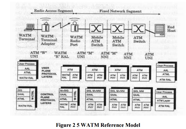
The WATM
system reference model, proposed by ATM Forum Wireless ATM (WATM) group,
specifies the signaling interfaces among the mobile terminal, wireless terminal
adapter, wireless radio port, mobile ATM switch and non-mobile ATM switch. It
also specifies the user and control planes protocol layering architecture. This
model is commonly advocated by many communication companies, such as NEC,
Motorola, NTT, Nokia, Symbionics, and ORL.
The major
components of a Wireless ATM system are: a) WATM terminal, b) WATM terminal
adapter, c) WATM radio port,
d) mobile ATM switch, e) standard ATM network and f) ATM host. The
system reference model consists of a radio access segment and a fixed network
segment. The fixed network is defined by "M (mobile ATM)" UNI and NNI
interfaces while the wireless segment is defined by "R (Radio)" radio
access layer (RAL) interface.
The "W" UNI is concerned with handover signaling, location management, wireless link and QoS control. The "R" RAL governs the signaling exchange between the WATM terminal adapter and the mobile base station. Hence, it concerns channel access, datalink control, meta-signaling, etc. The "M" NNI governs the signaling exchange between the WATM base station and a mobile capable ATM switch. It is also concerned with mobility-related signaling between the mobile capable ATM switches
c) BRAN
The broadband radio access networks (BRAN), which
have been standardized by the European Telecommunications Standards Institute
(ETSI), could have been an RAL for WATM (ETSI, 2002b). The main motivation
behind BRAN is the deregulation and privatization of the telecommunication
sector in Europe. The primary market for BRAN includes private customers and
small to medium-sized companies with Internet applications, multi-media
conferencing, and virtual private networks. The BRAN standard and IEEE 802.16
(Broadband wireless access, IEEE, 2002b) have similar goals.
BRAN standardization has a rather large scope
including indoor and campus mobility, transfer rates of 25–155 Mbit/s, and a
transmission range of 50 m–5 km. Standardization efforts are coordinated with
the ATM Forum, the IETF, other groups from ETSI, the IEEE etc. BRAN has
specified four different network types (ETSI, 1998a):
4. HIPERLAN 1: This high-speed WLAN supports mobility at data rates above 20 Mbit/s. Range is 50 m, connections are multi-point-to-multi-point using ad-hoc or infrastructure networks
5. HIPERLAN/2: This technology can be used for wireless access to ATM or IP networks and supports up to 25 Mbit/s user data rate in a point-to-multi- point configuration.
6. HIPERACCESS: This technology could be used to
cover the ‗last mile‘ to a customer via a fixed radio link, so
could be an alternative to cable modems
or xDSL technologies (ETSI, 1998c).
7. HIPERLINK: To connect different HIPERLAN access points or HIPERACCESS nodes with a high-speed link, HIPERLINK technology can be chosen.
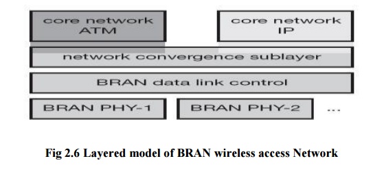
8. As an
access network, BRAN technology is independent from the protocols of the fixed
network. BRAN can be used for ATM and TCP/IP networks as illustrated in Figure.
Based on possibly different physical layers, the DLC layer of BRAN offers a
common interface to higher layers. To cover special characteristics of wireless
links and to adapt directly to different higher layer network technologies,
BRAN provides a network convergence sub layer. This is the layer which can be
used by a wireless ATM network, Ethernet, Fire wire, or an IP network. In the
case of BRAN as the RAL for WATM, the core ATM network would use services of
the BRAN network convergence sub layer.
HiperLAN2
While
HIPERLAN 1 did not succeed HiperLAN2 might have a better chance. HiperLAN2 offers more features in the mandatory
parts of the standard (HiperLAN2, 2002).
High-throughput transmission: Using OFDM in the physical layer and a
dynamic TDMA/TDD-based MAC protocol, HiperLAN2 not only offers up to 54 Mbit/s
at the physical layer but also about 35 Mbit/s at the network layer.
Connection-oriented: Prior to
data transmission HiperLAN2
networks establish logical connections between a sender and a receiver
Quality
of service support: support of QoS is much simpler. Each connection has its own set of QoS
parameters (bandwidth, delay, jitter, bit error rate etc.).
Dynamic
frequency selection: HiperLAN2 does
not require frequency
Security support: Authentication
as well as encryption are supported by HiperLAN2.
Mobility support: Mobile
terminals can move around while transmission always takes place between the terminal and the access point with
the best radio signal.
Application and network independence: HiperLAN2
was not designed with a certain
group of applications or networks in mind. Access points can connect to LANs
running ethernet as well as IEEE 1394 (Firewire) systems used to connect home
audio/video devices.
Power saves: Mobile terminals can negotiate
certain wake-up patterns to save power.
REFERENCE MODEL AND CONFIGURATIONS
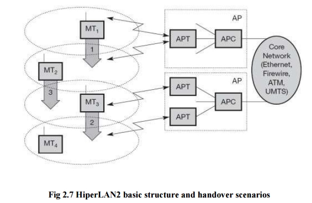
The above Figure shows the standard architecture of
an infrastructure-based HiperLAN2 network. Here, two access points (AP) are attached to a core network. Core networks
might be Ethernet LANs, Firewire (IEEE 1394) connections between audio and
video equipment, ATM networks, UMTS 3G cellular phone networks etc. Each AP
consists of an access point controller
(APC) and one or more access point
transceivers (APT).
An APT can comprise one or more sectors (shown as
cell here). Finally, four mobile
terminals (MT) are also shown. MTs can move around in the cell area as shown. No frequency planning is
necessary as the APs automatically select the appropriate frequency via dynamic frequency selection. Three
handover situations may occur:
Sector
handover (Inter sector): If sector antennas are used for an AP, which is optional in the standard, the AP
shall support sector handover. This type
of handover is handled inside the DLC layer
Radio
handover (Inter-APT/Intra-AP): As
this handover type,
too, is handled within the AP, no
external interaction is needed.
Network handover (Inter-AP/Intra-network): This is
the most complex
situation:
MT2 moves from one AP to another.
HiperLAN2
networks can operate in two different modes (which may be used simultaneously
in the same network).
Centralized mode (CM): In infrastructure-based
mode all APs are connected to a core network and MTs are associated with APs.
· Direct mode (DM): The
optional ad-hoc mode of HiperLAN2 directly exchanged between MTs if they can
receive each other, but the network still
controlled.
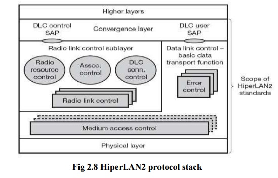
The above figure shows the HiperLAN2 protocol stack
as used in access points. Protocol stacks in mobile terminals differ with
respect to the number of MAC and RLC instances (only one of each). The lowest
layer, the physical layer, handles
as usual all functions related to modulation, forward error correction, signal detection, synchronization etc. The data link control (DLC) layer contains
the MAC functions, the RLC sub layer and error control functions. The MAC of an AP assigns each MT a certain
capacity to guarantee connection quality depending on available resources.
Above the
MAC DLC is divided into a control and a user part. The user part contains error control mechanisms. HiperLAN2
offers reliable data transmission using acknowledgements and retransmissions.
The radio link control (RLC) sub
layer comprises most control functions in the DLC layer (the CC part of an AP).
The association control function
(ACF) controls association and authentication of new MTs as well as
synchronization of the radio cell via beacons.
The DLC user connection control (DCC or
DUCC) service controls connection setup, modification, and release. Finally,
the radio resource control (RRC)
handles handover between APs and within an AP. On top of the DLC layer there is
the convergence layer. This highest
layer of HiperLAN2 standardization may comprise segmentation and reassembly
functions and adaptations to fixed LANs, 3G networks etc.