Chapter: Civil : Railway Airport Harbour Engineering : Railway Engineering : Rail Joints and Welding of Rails
Welding a Rail Joint methods used on railways
Welding a Rail Joint
The purpose of welding is to join
rail ends together by the application of heat and thus eliminate the evil
effects of rail joints. There are four welding methods used on railways.
(a) Gas
pressure welding
(b) Electric
arc or metal arc welding
(c) Flash
butt welding
(d) Thermit
welding
The
detailed descriptions of these methods are given below.
A.Gas Pressure Welding
In this type of welding, the
necessary heat is produced by the combination of oxygen and acetylene gases.
The rail ends to be welded are brought together and heat is applied through a
burner connected to oxygen and acetylene cylinders by means of regulators and
tubes. A temperature of about 1200 o C is achieved. At this temperature, the
metal of the rail ends melts, resulting in the fusion and welding together of
the ends.
The rails to be welded are
clamped at the wall by applying a pressure of 40 t pressure, heated to a
temperature of about 1200 o C to 1400 o C, and butted with an upset pressure of
about 20 t. Then the joint is again heated to a temperature of 850 o C and
allowed to cool naturally. It has been seen that this method of welding is
cheaper as compared to flash butt welding. The quality of this welding joint is
also claimed to be quite good. There are both stationary and mobile units
available for gas pressure welding.
The
process, though simple, has not yet been adopted on a large scale by Indian
Railways. The main reason behind this is its limited output and the difficult
and irregular availability of gas. India has only one plant that offers gas
pressure welding, which is located at Bandel on the ER (Eastern Railways) and
the progress in this plant has been nominal.
B.Electric or Metal Arc Welding
In this method, heat is generated
by passing an electric current across a gap between two conductors. A metal
electrode is energized by a voltage source and then brought close to another
metal object, thereby producing an arc of electric current between the two
objects. A lot of heat is generated by this electric arc, causing the two rail
ends to fuse or weld. This type of welding can be done using any of the
following methods.
(a) Insert
plate technique
(b) Scheron
process
(c) Enclosed
space technique
Indian Railways has recently
started welding rail joints using the metal arc process on a trial basis and
the performance so far has been satisfactory.
C. Flash Butt Welding
In flash butt welding, heat is
generated by the electric resistance method. The ends of the two rails to be
welded are firmly clamped into the jaws of a welding machine. One of the jaws
is stationary, while the other one is moveable and as such the gap between the
two rail ends can be adjusted. It is not necessary to specially prepare the
rail ends, though these can be preheated with an oxy-acetylene torch, if
necessary. The rail ends are brought so close together that they almost touch
each other. An electric current of 35 kA is passed between the interfaces of
the two rails, developing a voltage of 5 V. The rails are subjected to a
predetermined number of preheats (15 for 52-kg rails and 13 for 90 R rails)
before they are welded. A lot of flashing (sparking) occurs and considerable
heat is generated by the passage of electrical current between the rail ends.
The rail ends are automatically moved to and fro by the machine till the
temperature rises to a fusion limit in the range of 1000 o C to 1500 o C. At this
juncture, the rail ends are pressed together with an upset pressure of about 37
t and final flashing takes place joining the two rail ends together. The process
is so well regulated that any steel that might have been oxidized during the
preheating phases gets completely eliminated. The total time taken for welding
a joint is 150-200 sec and the loss in rail length is about 20 mm for each
weld. In the case of 90 R rails, the total welding time is 161 sec, which
includes a burn-off period of 20 sec, on-preheat time of 65 sec (13 � 5 sec),
off-preheat time of 36 sec (12 � 3 sec), and final flashing time of 40 sec.
High-quality welded joints are
produced by the flash butt welding method. The cost of a welded joint using
this method is also quite low compared to other methods of welding. The method,
however, can be adopted most economically and efficiently only in a workshop,
for which capital investment is required.
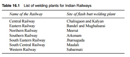
The flash
butt welding method is the standard method of welding of rails on Indian
Railways. Most railways have one or more flash butt welding plants where rails
are welded together. The existing plants for Indian Railways are listed in
Table 16.1.
Table
16.1 List of welding
plants for Indian Railways
The
stepwise procedure for the flash butt welding of rails is as follows.
Pre-straightening of rails The rails
are straightened before they are welded in order to ensure that the
welded rail has a good alignment.
End cleaning The ends of the rails are
cleaned for a length of 150-225 mm using electric or pneumatic grinders.
Adjustment of rail ends The rail
ends are then brought together in the flash butt welding machine and
longitudinally and vertically aligned by suitably adjusting the machine.
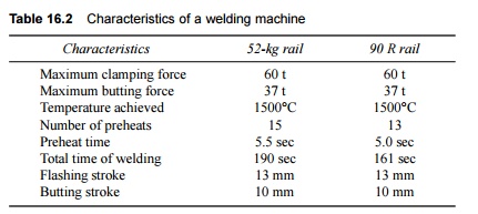
Welding The rail
ends are then welded in the flash butt welding machine. Most machines on
Indian Railways are those manufactured by A.I. Welders, Inverness, Scotland.
The important characteristics of a typical machine manufactured by A.I. Welders
are presented in Table 16.2.
Stripping As soon
as the rails are welded, they are made to pass through a stripping machine,
where all the extra metal, called upset metal, is chipped off.
Table
16.2 Characteristics
of a welding machine
Hot chipping In case
there is no stripping machine available, the extra material on the rail
head is chipped off manually using pneumatic chisels while the metal is still
hot.
Spray cooling After the
hot metal is chipped off, the rails are cooled by spray cooling.
Profiling The rails are then correctly
profiled.
Post straightening The rails
are straightened in the post straightening machine, which removes both horizontal
and vertical kinks, if any, so as to ensure perfect alignment in both
directions.
Ultrasonic inspection The rails
as well as the welds are examined to ensure that there are no flaws in
them. This is particularly important for second-hand rails.
Examination and inspection The rail
ends are finally examined and inspected with regard to specified
tolerances so that the welded surface has a good finish.
C.1 Output and Cost
The average time taken for
welding a joint is about 6 min. for 52-kg rails and 5.5 min. for 90 R rails,
and about 70-90 joints can be welded per 8-h shift. The flash butt welding
plant at Meerut (Northern Railways) welds about 160 joints per day by working
in double shifts. The approximate cost comes to about Rs 350 per weld including
overheads, depreciation charges, etc.
C.2 Welding Recorder
The quality of the welding can be
checked using a 'welding recorder', which automatically records all the
parameters that control the quality of a weld. The following parameters are
recorded by this device.
(a) Primary
amperage
(b) Voltage
(c) Butting
pressure
(d) Loss of
length
A graphical study of the records
of these parameters helps in judging the quality of the welding, after which
the desired action can be taken if any one of these parameters is found to be
improperly regulated. A few of these welding recorders have recently been
purchased by Indian Railways and are being used in flash butt welding plants.
C.3 Automatic Flash Butt Welding Machine
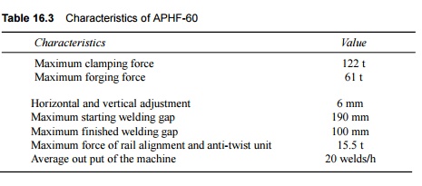
Indian Railways has procured a few
of the latest superior quality Mark IV type of flash butt welding machines
(APHF-60). The new design of this machine permits the welding of rails of
sections up to 60 kg/m or above made up of medium manganese and of the wear
resistant type. Most of the operations in this machine are automatic. These
machines are capable of aligning and de-twisting the rail end to facilitate the
formation of high-quality welded joints. The technical characteristics of this
machine are given in Table 16.3.
Table
16.3 Characteristics
of APHF-60
The new automatic flash butt
welding machine has many supplementary machines like th grinding machine, pre-
and post-straightening machines, the short blasting or brushing machine for end
cleaning, generators, etc. The cost of the ensemble of supplementary machines
is about Rs 90 million whereas the cost of the main welding machine is about Rs
40 million. The new welding machine is able to perform most of the operations
automatically and the time taken for welding a 52-kg rail is approximately 70
sec. The average output of the machine is 20 welds per hour.
C.4 Manual for Flash Butt Welding of
Rails
The code of practice for the
flash butt welding of rails has been standardized by Indian Railways from time
to time. The latest instructions in this regard are contained in the Manual
for Flash Butt Welding of Rails 1994. The manual describes the type and
suitability of the rails to be welded and the general procedure to be followed,
and enlists the tolerances for the finished joints as well as the acceptance
tests the joints must undergo to ensure quality control.
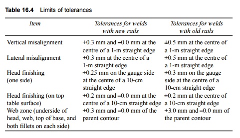
Tolerances for flash butt welded joints
Each completed flash butt welded
joint should be checked for its straightness, alignment, and finish using 1-m
and 10-cm-long straight edges. The permissible tolerances are given in Table
16.4. These tolerances also apply to thermit welded joints barring the web
zone, where the tolerance specified is +10 mm and -0.0 mm.
Table
16.4 Limits of
tolerances
Testing of rail joints
A rail joint should be tested for its strength and hardness
before it is considered acceptable for use in railways. The following tests are
prescribed on Indian Railways.
Transverse test One joint should be tested
using the transverse test daily before work starts in all flash butt
welding depots where there is no provision of welding recorders. In depots
where recorders have been provided, one in every 1000 joints should be tested
using the transverse test.
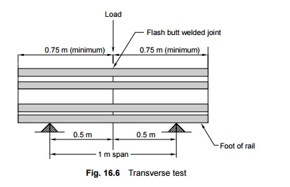
In the
transverse test, a 1.5-m-long test piece with a weld in the centre is taken and
placed on two cylindrical supports that have a diameter of 30 to 50 mm and are
placed 1 m apart. When pressure is applied in the form of a load at the centre
of the test piece, it should show the minimum recommended deflection without
any sign of cracking (Fig. 16.6).
Metallurgical test A macro
graphic examination of the flash butt weld is done after every 5000
welds. This test checks the presence of any porosity due to cracks, slag
inclusion, or other welding defects.
Hardness test A
hardness test may also be carried out for the welded head affected zone.
The Brinell hardness number (BHN) should be between 210 and 250, presuming that
the BHN of the parent rail is 230.
Ultrasonic flaw detection Every
joint is USFD (ultrasonic flaw detection) tested using normal 45 o /37 o ,
70 o , and 80 o probes to cover the head, web, and foot.
Fatigue test Testing is done for two
stress ranges with a 20% reversal. +27.5 kg/mm2 to -5.5 kg/mm
2 (range 33 kg/mm2)
+25 kg/mm2
to -5 kg/mm 2 (range 30 kg/mm2)
Welding of second-hand rails
Second-hand rails can be welded
conveniently in flash butt welding depots after being cropped for use on branch
lines. European countries implement the welding of second-hand rails on a large
scale in order to economize. The aspects that require particular attention in
the welding of second-hand rails are as follows:
(a) Checking
of the dimensions of old rails as per specifications
(b) Matching
the old rails
(c) Sawing
the rail ends
(d) Planing
the rail head
(e) Permissible
wear of the rails to be welded
(f) Marking
the gauge side
(g) Ultrasonic
inspection of the rails
DD. Thermit
Welding of Rails
This is the only form of site
welding which is being adopted universally. The method was first developed by
Gold Schmidt of Germany towards the end of the nineteenth century. A code of
practice for welding rail joints using the alumino-thermic process has been
developed by Indian Railways. The code defines the method of welding and the
precautions and steps to be taken before, during, and after welding for the
production of satisfactory weld joints.
D.1 General Principles
The principle behind this process
is that when a mixture of finely divided aluminium and iron oxide, called thermit
mixture, is ignited, a chemical reaction takes place which results in the
evolution of heat and the production of iron and aluminium oxide:
Fe2O3
+ 2Al = 2Al2O3 + 2Fe + heat
In this reaction, 159 g of iron
oxide combines with 54 g of aluminium to give 102 g of aluminium oxide, 112 g
of iron, and 182 kcal of heat. The reaction is exothermic and it takes about
15-25 sec to achieve a temperature of about 2450 o C.
The released iron is in the
molten state and welds the rail ends, which are kept enveloped in molten boxes.
The aluminium oxide, being lighter however, floats on top and forms the slag.
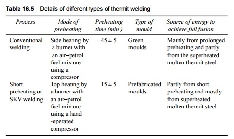
D.2 Different Types of Thermit Welding
There are
two types of alumino-thermic welding processes sanctioned for the welding of
rails on Indian Railways. These are conventional welding and SKV welding. SKV
is the short form of the German phrase 'Schweiss-Verfahran mit Kurz vorwarmung'
meaning the short preheat welding method. The technique is therefore also
termed SPW (short preheat welding). The Railway Board, as a matter of general
policy, has decided that the SKV welding technique should be introduced as soon
as possible on the Indian Railways. Table 16.5 gives the details of these two
types of thermit welding.
D.3 Thermit Welding Operations
Thermit welding involves the following operations.
(a) A special
type of moulding mixture is used to create moulds of the rail in halves. For
green moulds this moulding mixture is essentially high silica sand mixed with
bentonite sieved to the required gradation so that it is coarse enough to
permit ventilation. The sand should neither be too dry not too wet. It is mixed
with dextrin (a form of molasses) to make it as pliable as desired. The moulds
are clamped at the rail joint in such a way that there is adequate peripheral
clearance around the rail profile. Normally, green sand moulds are used for
conventional thermit welding and prefabricated carbon dioxide sand moulds are
used for SKV welding.
(b) After
fixing and luting the moulds, the rail ends are heated with a blue flame so as
to attain a temperature of 950 o C to 1000 o C for the conventional process and
600 o C for the short preheating process. In case of conventional welding,
heating should be continued till the rail ends have turned yellowish red or
orange, which can be checked visually through a coloured glass.
An opening is provided in the mould through which
heat is supplied by the means of burners that use any one of the following
fuels:
(i) air and
petrol
(ii) oxygen
and cooking gas (LPG-liquefied petroleum gas)
(iii) oxygen
and propane.
The time taken for preheating is about 30-45 minutes
for conventional welding and 10-12 minutes for short preheating (SKV) welding.
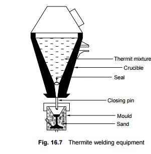
(c) A special
type of crucible lined with magnetite is fixed near the rail joint in such a
way that, when required, it can be swung round and brought exactly over the
joint. A hole is provided in the bottom of the crucible which is plugged with a
closing pin and has asbestos wool sprinkled over it to protect it from the
molten steel. Powdered slag is then strewn over the asbestos wool so that it
lies undisturbed. (Fig. 16.7).
(d) The
thermit mixture is then placed inside the crucible. About 4-7 kg of the mixture
is required for conventional thermit welding and about 9.0-15 kg of it is
required for SKV welding.
(e) As soon
as preheating is completed, the thermit mixture is ignited using special
igniters made up of barium peroxide and aluminium. A violent reaction takes
place in the crucible that leads to the evolution of heat, and the thermit
mixture turns into a molten bath. The slag, being lighter, floats to the top
and the molten iron remains at the bottom. The reaction takes place for about
15-25 sec and an extra margin of about 5 sec is kept for the separation of the
slag. A temperature of about 2540 o C is reached during the process.
(f) The
crucible is then swung round and the closing pin is taped up. Molten iron flows
down and fills the peripheral area around the mould. The crucible is then swung
further and the slag flows out.
(g) The
molten thermit steel fuses around the preheated surface of the rail ends and a
homogeneous weld is made.
(h) The
moulds are removed after about 5 min. When demoulding, only the head, and not
the foot and the web, should be exposed. The excess metal is chipped off from
top of the rail and the gauge face while it is still red hot.
D.4. Post-welding
Operations
The following operations are
carried out after the welding of the rail ends is complete.
(a) The rail
ends are cooled for 3-4 min.; controlled cooling is required for alloy steel
rail joints.
(b) In order
to ascertain that the rail profile is correct, the finish of the welded joint
is achieved either by the use of hand files or portable grinders.
(c) The
welded joint is now ready. The sleepers are shifted to their original positions
and properly packed. At least 30 min. should have elapsed since the pouring of
the metal before the first train is allowed to pass on the welded joint.
(d) The USFD
testing of new welds made by thermit welding should be completed within 30 days
of executing the welds.
The thermit process is a very
convenient form of welding for times when work needs to be carried out work at
the site. No extra power is required and there is enough heat generated during
the chemical reaction. The welded joint, however, is found to be weak in
strength as compared to the flash butt welded joint. The conventional process
has generally been abandoned on Indian Railways to pave way for the short preheat
process.
D.5 Short Preheat Thermit Welding
Technique
The short preheat welding (SPW or
SKV) method has recently been developed by Indian Railways for medium
manganese, wear resistant, and special alloy rails. With this technique, it is
possible to reduce the total time taken for welding and chipping by about 30
minutes.
The main feature of this
technique is that only a length of 3-5 mm at each end of the rails to be welded
is heated to a temperature of 6000 o C, as against the heating of the entire
cross section of the rail to 1000 o C over a length of 10-15 mm in the
conventional method of thermit welding. The large quantity of heat necessary
for heating the rail ends is supplied by the use of a large quantity of thermit
mixture.
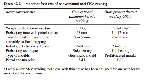
D.6 Conventional Welding Versus SKV
Welding
The salient features of
conventional thermit welding in the case of 52-kg medium manganese rails versus
those of short preheat welding are listed in Table 16.6.
Table
16.6 Important
features of conventional and SKV welding
D.7 Precautions During Thermit Welding
In order to ensure the quality of
thermit welded joints, the following precautions should be taken.
Follow prescribed procedure Thermit
welding of joints should be carried out strictly as per the prescribed
norms. The horizontal and vertical alignment of two rail ends require special
attention at the joint. In particular, case should be taken to see that the
rail ends are square and that their alignment is perfect.
Equipment in good order All the
relative equipment and gadgets should be in working order and be
available at the site. The important welding equipment and gadgets are rail
thermometer, rail tensor, stop watch, 10-cm straight edge, feeler gauge,
leather glove, blue goggles, wire brush, slag container, spatula, and first aid
box.
Qualified welder Thermit
welding should be done only by a qualified welder who holds a valid
competency certificate.
Effective supervision Thermit
welding should be done only under the supervision of a qualified PWI/PWM
(permanent way inspector/permanent way mistry) with a valid competency
certificate.
End cropping Second-hand
rails should not be welded before their ends have been cropped. The rail
ends should be cropped vertically and thoroughly cleaned with kerosene oil with
the help of a brush.
Proper gaps In order
to get good results, proper gaps should be ensured between the two rails
to be welded. The standard gaps recommended are the following:
Conventional welding 11 � 1 mm
SPW or SKV welding 24 � 1 mm
50-mm welding 50 � 2 mm
Adequate block When the
conventional method is used for the thermit welding of rails on a
running line, the work should normally not be completed in a time block of less
than 75 min. In the case of SKV/SPW welds, the same work should not be done in
a block of less than 50 minutes.
Use of rail tensor A rail
tensor must be used for maintaining the correct gap when thermit welding
rails in a decreasing range of temperature and also when repair welding on
LWR/CWR (long welded rail/continuous welded rail) tracks. In the case of repair
welding, 100 m on either side of the weld should be destressed in order to get
good results.
Work to be done on cess In the
field, thermit welding should be done on the cess as far as possible to
ensure the quality of the welded joints. Luting should be done after ensuring
that the moisture content is minimum so as to improve the quality of the weld.
In the case of cess welding, rails should be supported by about 10 wooden
blocks under each rail seat.
Adequate
pressure Welding should normally be done at a pressure of 100-110 psi.
The time taken for preheating should normally be about 10-12 minutes.
Use of wooden planks The
portion of the rail to be welded should be kept on wooden planks to
ensure that moisture does not enter these portions.
Finishing of joint After
welding, the joint should be given a proper finish on both the gauge as
well as the non-gauge side and any extra collar should be removed in order to
enable SFD testing.
Joggled fish plate After
thermit welding of LWR, the joint should be joggle fish plated and
supported on wooden blocks till it has cleared the USFD test.
D.8 Testing of Thermit Welded Joints
A rail joint should be tested for
its strength and hardness before it can be accepted for use on the railways. To
this end, the following tests are prescribed on Indian Railways.
Reaction test The
characteristic reaction of the thermit mixture when it is placed in a
standard crucible is scrutinized to ensure that it conforms to the specified
standards. The alumino-thermit steel is extracted out of the melted metal and
its chemical composition is determined. The aluminium content should be between
0.3% and 0.7%. The reaction test should be carried out on the mixture for every
250 portions or part thereof.
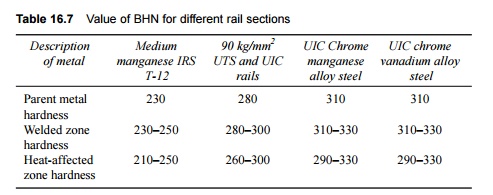
Hardness test The
Brinell hardness test is carried out in welded zones, in heat-affected zones,
on the parent metal of the rail, and at the top and sides of the head of the
test weld using a 3000-kg load and 10-mm-diameter ball for 10 sec. The average
Brinell hardness number (BHN) for welded and heat-affected zones as well as for
the parent metal of different rail sections should be as given in Table 16.7.
Table
16.7 Value of BHN for
different rail sections
Transverse breaking load test The test
weld is positioned on cylindrical or semi-cylindrical supports of diameter
30-50 mm at a distance of 1 m from centre to centre, with the weld placed at the
centre of the span and loaded in such a manner that the foot of the rail is in
tension. The load is gradually increased till a rupture occurs in the weld. The
test weld should withstand the minimum deflection that has been specified for
all the different sections and types of rails.
One out of every 100 welded
joints should be picked up at random and be subjected to both the hardness and
transverse tests. For 90 UTS rails weighting 50-60 kg/m, the minimum breaking
load is 80 t with a minimum deflection of 15 mm at the centre. The tolerances for the various
dimensions of thermit welded joints are the same as specified for flash butt
welded joints.
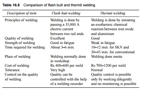
The important features of flash
butt welding and thermit welding are compared in Table 16.8.
Table
16.8 Comparison of
flash butt and thermit welding
Related Topics