Chapter: Microprocessor and Microcontroller : Micro Controller Programming & Applications
Washing Machine Control Interfacing with 8051 Micro Controller
Washing Machine Control
Many
washing m/c shell in the market has mechanical controlled sequence for
activated the timer and the sequence back and forth for their motor; washing
motor or spinning motor. Spinning motor control only has one direction only,
and its simple could be changed to the discrete mechanical timer which sell on
the market. But washing motor control has 2 direction for this purpose, it
means to squeeze the clothes, it must go to forward and then reversed. The
sequence is like this:
ü First, go
to forward direction for about a few seconds
ü Than
stop, while the chamber is still rotate
ü Second,
go back to reverse direction for about a few seconds
ü Than
stop, while the chamber is still rotate
ü And so
on, back and forth, until the the timer elapsed
1 Schematic
Timing
sequence like the above description, can be implemented with many way, by using
discrete electronic components, timer, using a program or a microcontroller or
microprocessor, etc. Because I am learning the PIC microcontroller for right
now, I will implement this function using this microcontroller, but for you who
familiar with another kind of microcontroller my adapted it to your purpose. By
using PIC micro, it can be made more compact. First I plan to make 2 buttons, 1
for set the timer and another for reset the timer or for the emergency stop
push button. Then to know the timer works or not, I need a visual display.
For this
purpose I will use 7-segmen display showing the rest of the timer. To run the
motor sequence of course I need a pair of relays (power relays, about 3 Amperes
output), one for forward and another for reverse option. I will use the very
common family of PIC micro, ie : 16F84A, because this is the most popular type
and very simples used and very much used. Also can be obtained easily in the
market. But this is the medium type of PIC micro family. It has 1kByte of
memory (EEPROM type) and 13 I/O pins. It can be reprogrammable thousands times.
Because the I/O just only 13 pins, I used a BCD to 7-segmen chip. So it will
left a few I/O pins for expanded in the future. You can omitted this chip for
timing sequence purpose and save one IC price, because the I/O just exactly
enough.
ü I/O port
A-0 = SET push button
ü I/O port
A-1 = RST push button
ü I/O port
A-2 = Reserved
ü I/O port
A-3 = Reserved
ü I/O port
A-4 = Reserved
ü I/O port
B-0 = Forward Relay (Run motor forward)
ü I/O port
B-1 = Reverse Relay (Run motor reverse)
ü I/O port
B-2 = Activated unit 7-segmen (multiplexed)
ü I/O port
B-3 = Activated ten 7-segmen (multiplexed)
ü I/O port
B-4 = BCD data A (for 7-segmen)
ü I/O port
B-5 = BCD data B (for 7-segmen)
ü I/O port
B-6 = BCD data C (for 7-segmen)
ü I/O port
B-7 = BCD data D (for 7-segmen)
ü Also
integrated power supply to run it modularly
The I/O
can be configured as input pin or output pin bit-ly. It is up to you to choose
the I/O pin number goes to what function, but it infect the program firmware of
course. Once you choose, then it is just like that, except you also change
both, the program and the hardware.
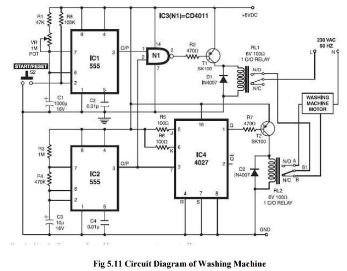
2 Working of Washing Machine
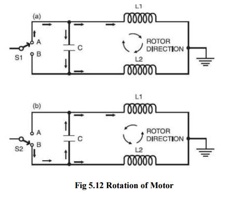
The
direction of rotation can be controlled when switchS1 is in position A, coil L1
of the motor receives the current directly, whereas coil L2 receives the current
with a phase shift due to capacitor C. So the rotor rotates in clockwise
direction (see Fig. 2(a)). When switch S1 is in position B, the reverse happens
and the rotor rotates in anti-clock wise direction Thus switch S1 can change
the rotation direction. The motor cannot be reversed instantly. It needs a
brief pause between switching directions, or else it may get damaged. For this
purpose, another spin direction control timer (IC2) is employed. It is realised
with an IC 555. This timer gives an alternate „on‟ and „off‟ time duration of
10 seconds and 3 seconds, respectively. So after every l0 seconds of running
(either in clockwise or anti clockwise direction), the motor stops for a brief
duration of 3 seconds. The values of R3 and R4 are calculated accordingly. The
master timer is realised with monostable IC555 (IC1) and its „on‟ time is
decided by the resistance of 1-mega- ohm potmeter VR. A 47-kilo-ohm resistor is
added in series so that even when the VR knob is in zero resistance position,
the net series resistance is not zero
Related Topics