Chapter: Microprocessor and Microcontroller : Micro Controller Programming & Applications
LCD and Seven Segment Disply Interfacing with 8051 Micro Controller
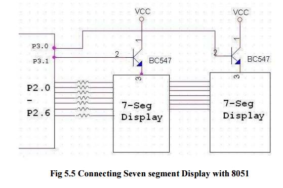
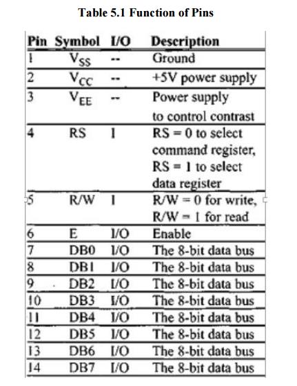
Seven Segment Disply Interfacing
with 8051
LCD Interfacing
This
section describes the operation modes of LCDs, then describes how to program
and interface an LCD to an 8051 using Assembly and C.
LCD operation:
In recent
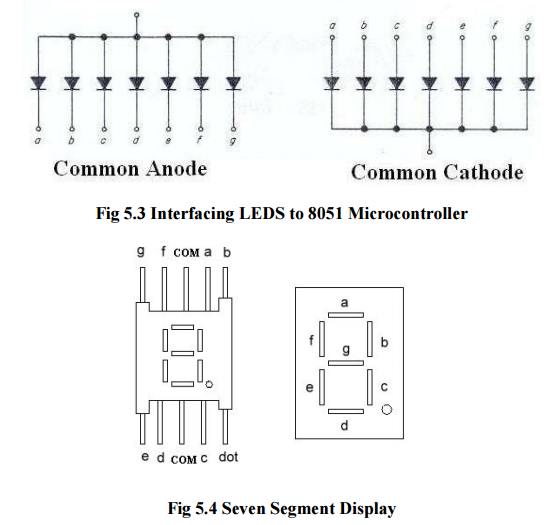
years the LCD is finding widespread use replacing LEDs (seven-segment LEDs or
other multisegment LEDs). This is due to the following reasons:
The declining prices of LCDs.
The ability to display numbers,
characters, and graphics. This is in contrast to LEDs, which are limited to
numbers and a few characters.
Incorporation of a refreshing
controller into the LCD, thereby relieving the CPU of the task of refreshing
the LCD. In contrast, the LED must be refreshed by the CPU (or in some other
way) to keep displaying the data.
Ease of programming for characters and
graphics.
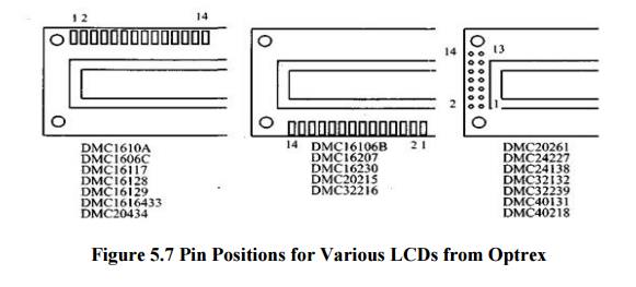
LCD pin descriptions
The LCD
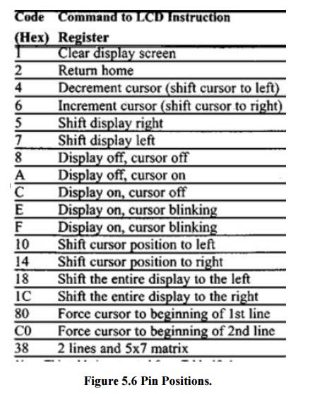
discussed in this section has 14 pins. The function of each pin is given in
Table 5-1. Figure 5.6 shows the pin positions for various LCDs.
VCC> VSS> and VEE
While Vcc
and Vss provide +5V and ground, respectively, VEE is used for controlling LCD
contrast.
RS, register select
There are
two very important registers inside the LCD. The RS pin is used for their
selection as follows. If RS = 0, the instruction command code register is
selected, allowing the user to send a command such as clear display, cursor at
home, etc. If RS = 1 the data register is selected, allowing the user to send
data to be displayed on the LCD.
R/W, read/write
R/W input
allows the user to write information to the LCD or read information from it.
R/W = 1 when reading; R/W = 0 when writing.
E, enable
The
enable pin is used by the LCD to latch information presented to its data pins.
When data is supplied to data pins, a high-to-low pulse must be applied to this
pin in order for the LCD to latch in the data present at the data pins. This
pulse must be a minimum of 450 ns wide.
DO-D7
The 8-bit
data pins, DO - D7, are used to send information to the LCD or read the
contents of the LCD's internal registers. To display letters and numbers, we
send ASCII codes for the letters A - Z, a - z, and numbers 0 - 9 to these pins
while making RS = 1.
There are
also instruction command codes that can be sent to the LCD to clear the display
or force the cursor to the home position or blink the cursor. Table 12-2 lists
the instruction command codes. We also use RS = 0 to check the busy flag bit to
see if the LCD is ready to receive information. The busy flag is D7 and can be
read when R/W = 1 and RS = 0, as follows: if R/W= 1, RS = 0. When D7 = 1 (busy
flag = 1), the LCD is busy taking care of internal operations and will not
accept any new information. When D7 = 0, the LCD is ready to receive new
information. Note: It is recommended to check the busy flag before writing any
data to the LCD.
Sending commands and data to LCDs with a
time delay
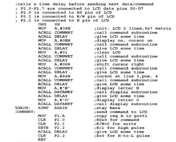
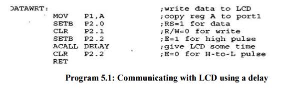
Program 5.1: Communicating with LCD using a delay
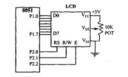
To send
any of the commands from Figure 5.6 to the LCD, make pin RS = 0. For data, make
RS = 1. Then send a high-to-low pulse to the E pin to enable the internal latch
of the LCD. This is shown in Program 5-1. See Figure 5.7 for LCD connections.
Program 5.2 Sending code or data to the LCD with
checking busy flag
The above
code showed how to send commands to the LCD without checking the busy flag.
Notice that we must put a long delay between issuing data or commands to the
LCD. However, a much better way is to monitor the busy flag before issuing a
command or data to the LCD. This is shown in Program 5.3.
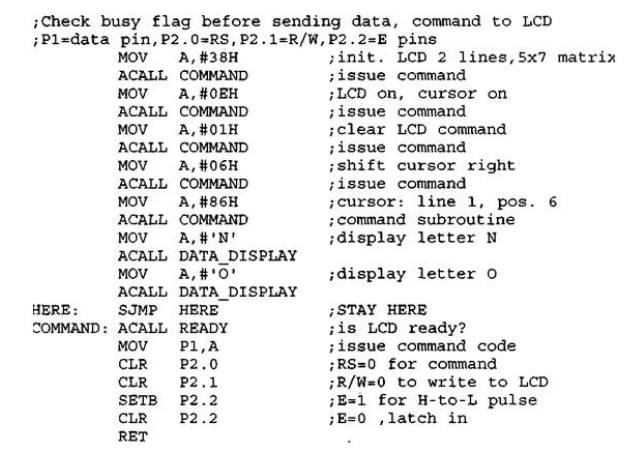
Program 5.3: Communicating with LCD using the busy
flag
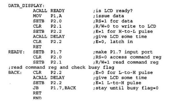
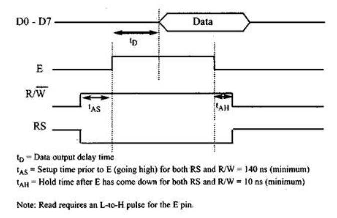
Figure 5.8. LCD Timing for Read (
L-to-H for E line)
Notice in
the above program that the busy flag is D7 of the command register. To read the
command register we make R/W = 1 and RS = 0, and a L-to-H pulse for the E pin
will provide us the command register. After reading the command register, if
bit D7 (the busy flag) is high, the LCD is busy and no information (command or
data) should be issued to it. Only when D7 = 0 can we send data or commands to
the LCD. Notice in this method that no time delays are used since we are
checking the busy flag before issuing commands or data to the LCD.
Contrast
the Read and Write timing for the LCD in Figures 5.8 and 5.9. Note that the E
line is negative-edge triggered for the write while it is positive-edge
triggered for the read.
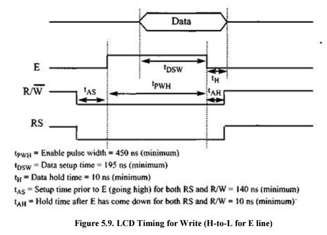
Figure 5.9. LCD Timing for Write
(H-to-L for E line)
LCD data sheet
In the
LCD, one can put data at any location. The following shows address locations
and how they are accessed.
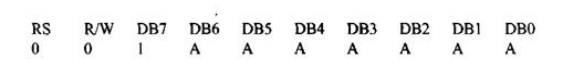
where
AAAAAAA = 0000000 to 0100111 for line 1 and AAAAAAA - 1000000 to 1100111 for
line 2. See Table 12-3.
Table 5.3 LCD Addressing
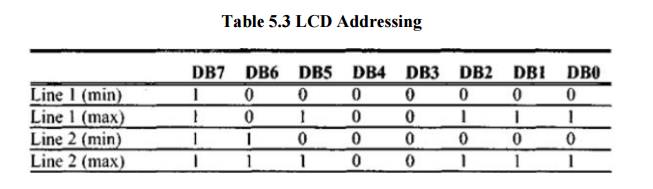
The upper
address range can go as high as 0100111 for the 40-charac-ter-wide LCD, while
for the 20-character-wide LCD it goes up to 010011 (19 decimal = 10011 binary).
Notice that the upper range 0100111 (binary) = 39 decimal, which corresponds to
locations 0 to 39 for the LCDs of 40x2 size.
From the
above discussion we can get the addresses of cursor positions for various sizes
of LCDs. See Figure 12-5 for the cursor addresses for common types of LCDs.
Note that all the addresses are in hex. Table 12-4 provides a detailed list of
LCD commands and instructions. Table 12-2 is extracted from this table.
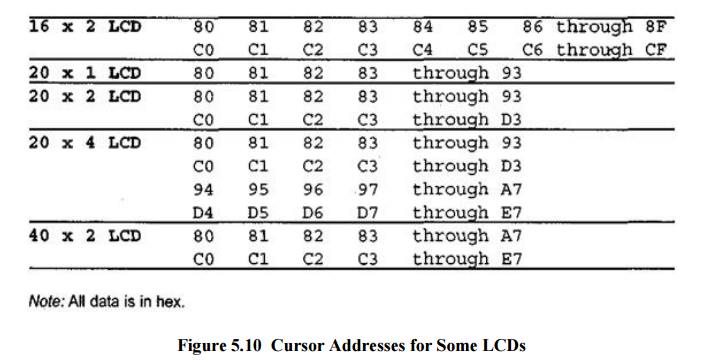
Figure 5.10 Cursor Addresses for Some LCDs
Related Topics